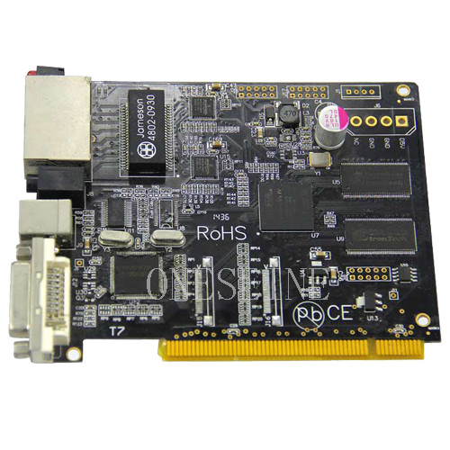
PCBA Manufacturing BGA HDI PCB JlCpcb Assembly With SMT Service
Basic information:
Layer:6
Material:Rogers+fr4
Surface finish:HASL lead free
Copper weight:1OZ
Board thickness:1.5mm
HS Code: 8534001000
Application: Communication
PCB Design Services: Yes
Prototypes Run: Yes
Our Multilayer PCB and PCBA capability and services:
SMT/THT/DIP.
1. Component Purchasing Service
2. SMT assembly and Through hole components insertion
3. IC pre-programming / Burning on-line
4. Function testing as requested
5. Complete Unit assembly (which including plastics, metal box, Coil, cable inside etc)
6. Packing design
Multilayer PCB assembly OEM & ODM Orders are Welcome.
We have in-house workshop for one stop shop service
OEM (We manufacture according to your design - BOM, Gerber file and testing procedures, while providing you best recommendations for easy manufacturing and cost saving):
1. Component sourcing and procurement
2. PCB Manufacturing
3. Component Assembly (PCBA - SMT & Through Hole parts)
4. Chip-on-board (COB)
Surface-mount technology (SMT)
Ball-grid array (BGA)
Through-hole
5. Plastic Enclosure (Mould) Manufacturing
6. Metal Enclosure (Tool) Manufacturing
7. Cable & Wire harness Assembly
8. Final Assembly
9. QC Testing
10.Packaging
The PCB assembly process typically includes the following steps:
Component Procurement: The required electronic components are sourced from suppliers. This involves selecting components based on specifications, availability, and cost.
PCB Fabrication: The bare PCBs are manufactured using specialized techniques such as etching or printing. The PCBs are designed with copper traces and pads to establish electrical connections between the components.
Component Placement: Automated machines, called pick-and-place machines, are used to accurately place surface mount components (SMD components) on the PCB. These machines can handle a large number of components with precision and speed.
Soldering: Once the components are placed on the PCB, soldering is performed to establish electrical and mechanical connections. There are two common methods used for soldering: a. Reflow Soldering: This method involves applying solder paste to the PCB, which contains small solder balls. The PCB is then heated in a reflow oven, causing the solder to melt and create connections between the components and the PCB. b. Wave Soldering: This method is typically used for through-hole components. The PCB is passed over a wave of molten solder, which creates solder connections on the bottom side of the board.
Inspection and Testing: After soldering, the assembled PCBs undergo inspection to check for defects, such as solder bridges or missing components. Automated optical inspection (AOI) machines or human inspectors perform this step. Functional testing may also be conducted to ensure the PCB operates as intended.
Final Assembly: Once the PCBs pass inspection and testing, they can be integrated into the final product. This may involve additional assembly steps, such as attaching connectors, cables, enclosures, or other mechanical components.
Certainly! Here are some additional details about PCB assembly:
Surface Mount Technology (SMT): Surface mount components, also known as SMD (Surface Mount Device) components, are widely used in modern PCB assembly. These components have small footprints and are mounted directly onto the surface of the PCB. This allows for higher component density and smaller PCB sizes. SMT components are typically placed using automated pick-and-place machines, which can handle components of various sizes and shapes.
Through-Hole Technology (THT): Through-hole components have leads that pass through holes in the PCB and are soldered on the opposite side. While SMT components dominate modern PCB assembly, through-hole components are still used for certain applications, especially when components require extra mechanical strength or high power handling capabilities. Wave soldering is commonly used for soldering through-hole components.
Mixed Technology Assembly: Many PCBs incorporate a combination of surface mount and through-hole components, referred to as mixed technology assembly. This allows for a balance between component density and mechanical strength, as well as accommodating components that are not available in surface mount packages.
Prototype vs. Mass Production: PCB assembly can be performed for both prototype and mass production runs. In prototype assembly, the focus is on building a small number of boards for testing and validation purposes. This may involve manual component placement and soldering techniques. Mass production, on the other hand, requires high-speed automated assembly processes to achieve efficient and cost-effective production of large quantities of PCBs.
Design for Manufacturing (DFM): DFM principles are applied during the PCB design phase to optimize the assembly process. Design considerations such as component placement, orientation, and proper clearances help ensure efficient assembly, reduce manufacturing defects, and minimize production costs.
Quality Control: Quality control is an integral part of PCB assembly. Various inspection techniques are employed, including visual inspection, automated optical inspection (AOI), and X-ray inspection, to detect defects such as solder bridges, missing components, or incorrect orientations. Functional testing may also be conducted to verify the proper operation of the assembled PCB.
RoHS Compliance: Restriction of Hazardous Substances (RoHS) directives restrict the use of certain hazardous materials, such as lead, in electronic products. PCB assembly processes have adapted to comply with RoHS regulations, using lead-free soldering techniques and components.
Outsourcing: PCB assembly can be outsourced to specialized contract manufacturers (CMs) or electronic manufacturing service (EMS) providers. Outsourcing allows companies to leverage the expertise and infrastructure of dedicated assembly facilities, which can help reduce costs, increase production capacity, and access specialized equipment or expertise.