Specifications
Place of Origin :
Shenzhen,China
Brand Name :
ONESEINE
Certification :
ISO9001,ISO14001
Model Number :
ONE-102
MOQ :
1pcs
Price :
USD0.1-1000
Packaging Details :
Vacuun bag
Delivery Time :
5-8 working days
Payment Terms :
T/T, Western Union
Supply Ability :
1000000000pcs/mon
Layer :
6
Material :
Rogers RO4350B + FR4 Hybrid
Type :
High Frequency PCB
Min Line Space :
4mil
Hole :
resin plug hole
Min. Line Width/Spacing :
4mil/4mil
Panel :
1*1
Solder Mask Type :
Liquid Photo Imageable (LPI)
Min. Hole Size :
0.2mm
Board Thickness :
Mechanical drill: 8mil(0.2mm)
Panel Size :
3*2
Layers :
4350+4450F
Description

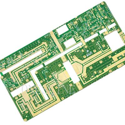
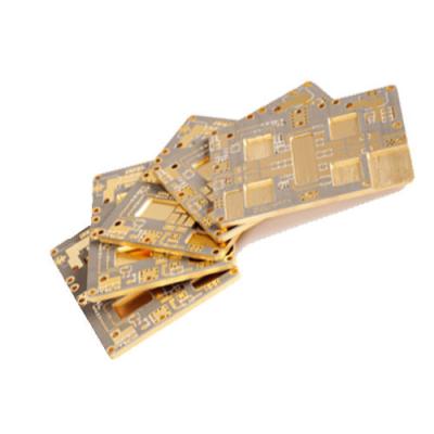
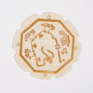
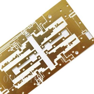
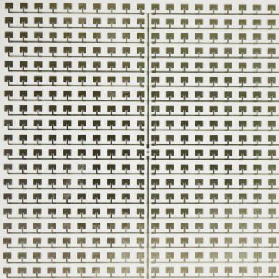
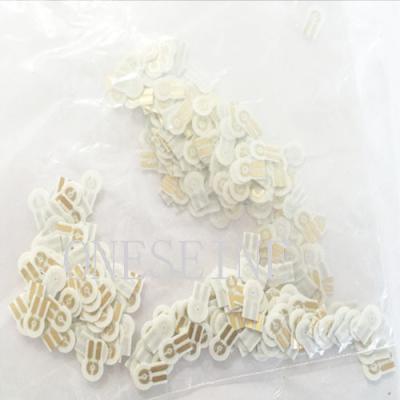
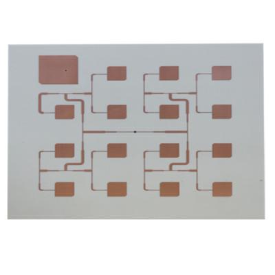
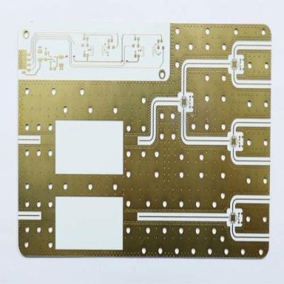
6L Rogers RO4350B Fr4 Hybrid High Frequency PCB Board

PCB parameter:

Material:Rogers RO4350B

Layers:6

Board thickness:1.6mm

Copper:1OZ

Dielectric thickness:0.508mm

Dielectric constant:3.48

Thermal conductivity:0.69w/m.k

Flame retardant rating:V-0

Volume resistivity:1.2*1010

Surface resistivity:5.7*109

Density:1.9gm/cm3

Surface finish:Immersion gold

Application: Radio frequency communication

Rogers PCB description:

Rogers PCB refers to printed circuit boards (PCBs) that are made using Rogers Corporation's high-performance materials. Rogers Corporation is a global leader in engineered materials for various industries, including electronics.

Rogers PCBs are widely used in applications that require high-frequency performance, excellent electrical properties, and thermal stability. The Rogers materials used in these PCBs have unique characteristics, such as low dielectric loss, high dielectric constant, and excellent signal integrity.

The most popular Rogers material for PCBs is Rogers RO4000 series, which includes materials like RO4350B, RO4003C, and RO3003. These materials are commonly used in high-frequency applications, such as wireless communication systems, radar systems, aerospace, and satellite systems.

Rogers PCBs offer several advantages, including low insertion loss, low signal distortion, and high reliability. They provide better performance at high frequencies compared to standard FR-4 PCBs. However, Rogers PCBs are typically more expensive than traditional PCBs due to the specialized materials used.

When designing and manufacturing Rogers PCBs, it's important to work with experienced PCB manufacturers who are familiar with the specific requirements and handling of Rogers materials. They can help ensure proper material selection, stack-up design, and manufacturing processes to achieve the desired electrical performance.

It's worth noting that the information provided here is based on the knowledge available up until September 2021. For the most up-to-date information on Rogers PCBs and materials, I recommend consulting Rogers Corporation's official website or contacting a reputable PCB manufacturer.

ROGERS RF PCB DESIGN AND MANUFACTURING PROCESS


How to design a good RF PCB Layout? Simple tips to design RF PCB layout. In this section, we will discuss the simple tips when you want to design a PCB layout for RF applications with rogers pcb material. Tips provided here don’t include talking about Smith charts, Q factor, S parameters, etc which need a lot of academic knowledge. Instead, we will discuss “the simple way” to design the RF PCB layout. Below are some simple tips to start with:
1. No single-shot perfect RF layout. If your design (e.g. antenna) does not perform as expected in your simulations, it is perfectly normal. It could happen because the antenna impedance is influenced by components located around it, and the impedance may shift in a way that cannot be predicted in software simulations. The best that you can do is adding a matching network that lets you tune the antenna in your final product. Moreover, not only antennas that require impedance matching, but also between different RF components or subsections on board need it for proper interfacing. And of course, iteration is a key!
2. Use 4-Layer Design. Multi-layer PCB is best. It’s not obligatory to use 4 layers in RF design. You can do the 2-layer design but you need to read some advanced RF concepts. If it is quite hard for you to make an advanced RF study of your circuit or because it takes so much time, then you can use 4-layer design as a solution. Don’t forget to put continuous grounds under traces. And consider material selection carefully. Standard FR-4 may not meet your needs (we will discuss more another material in the next section). Lastly, follow the signal stack below.
3. Make everything 50 ohms. Just in case it is your first time to design RF PCB layout and there is no available proper tools to simulate your design in 3D, then the best alternative that you can try is choosing components that have a characteristic impedance of 50 ohms on RF ports. Why 50 ohm? Because 50 ohm is the best value to do impedance matching. This includes a microstrip impedance calculation to know it’s resistance. Moreover, you can adjust the trace width properly to make the trace impedance on your PCB that carries RF signals becomes 50 ohms. You can calculate the trace width using online trace impedance calculators or microstrip impedance calculators. You can also use a CPWG (coplanar-waveguide-over-ground) structure to build 50Ω RF traces on PCBs. Lastly, actually it is quite easy to find components (such as antennas, filters, amplifiers, etc), with 50 ohms characteristic input/output impedance, for your project.
4. Lay out RF first – ALWAYS. RF traces are the first priority that you have to care about since it is EXTREMELY high frequency signal carrying structures. That’s why, if you put them at last, or if you try to put them when the board has already gotten rather clumsy, you will make compromises with the trace layout. And it can ended up make your design fail. Lastly, please make sure to have sufficient space around the signal trace for smooth bends and isolation of the RF signal.
5. Isolation is important. Isolating an RF trace is important. Ensure to make RF traces appropriately isolated from other high-speed signals (such as HDMI, Ethernet, USB differential pairs, clock traces for crystals, etc). Commonly, it is employed by “via stitching”. For example, do stitching vias around the RF trace to prevent it from interfering with other components on board. Please remember that inappropriate isolation will not render your design defunct. However, it will deteriorate the receiver performance and the average data throughtput in most cases. Therefore, utilize isolated vias for separate parts of a filter or matching network.
6. Keep inductance low. The ground inductance can cause a huge impact in your RF design. Grounding RF chipset through a single via or narrow ground trace could cause a massive ground inductance. And as we know, high-frequency does not like inductance. Therefore, do not forget to ground the RF chipset adequately. If the RF chipset is a QFN with ground pad, use at least 9 power vias. Then ensure a large and continuous ground plane under the chip and RF trace as well. If you have a free space on the top layer, do not forget to add a ground fill that is connected to the inner ground layer through as many vias as practically possible. But of course, don’t add a thousand vias! It would make a lot of pains to your PCB manufacturer. Lastly, use least number of vias in RF routing, max number of vias in RF grounding.
7. Use Plating/Copper. Use gold plating for RF components created from etch, with no copper inlands near the RF circuitry and no copper thieving near the RF circuitry. Then, ground both ends of copper pours, and stitch many vias wherever possible. The last, separate RF planes from all other planes.
8. Routing. For routing in RF PCB design, there are some points that you need to consider: (1) orient sensitive traces orthogonally, (2) use short traces between the crystal and RF device, (3) keep interconnect traces separated as much as possible, (4) keep trace lengths to a minimum, and (5) adhere to proper corner routing. Below are some types of corner routing.
9. Don’t break the ground plane. Maybe sometimes you find a case when you have to design an RF system where you also have an audio or analog circuitry on the same circuit board, and the audio or analog circuitry is close to RF system. You may be trying to have a different ground plane to isolate the ground for the audio or analog part. But by doing that, you probably will make your RF section severely. And remember that if you break the ground plane under the RF trace, you may have a design that does not work. Therefore, here is an example of what you should NOT do

Rogers PCB applications.

Moreover, since nowadays 5G Technology developments are growing quickly, various devices request high-frequency PCBs and RF PCBs with high performance which need not only low electrical noise but also low signal losses. And Rogers PCB material is a perfect choice to match the technological characteristics, besides it is also cost-effective for this purpose. Some Rogers PCB applications are:

1 .Automotive Radar and Sensors

2. Microwave equipment of all kinds.

3. Cellular Base Station Antennas

4. RF Identification (RFID) Tags

5. 5G Station

6. Microwave point to point (P2P) links

7. LNB’s for Direct Broadcast Satellites

6L Rogers RO4350B Fr4 Hybrid Rogers Pcb Material Circuit Board

Send your message to this supplier
Send Now

6L Rogers RO4350B Fr4 Hybrid Rogers Pcb Material Circuit Board

Ask Latest Price
Watch Video
Place of Origin :
Shenzhen,China
Brand Name :
ONESEINE
Certification :
ISO9001,ISO14001
Model Number :
ONE-102
MOQ :
1pcs
Price :
USD0.1-1000
Contact Supplier
video
6L Rogers RO4350B Fr4 Hybrid Rogers Pcb Material Circuit Board

ONESEINE TECHNOLOGY CO.,LTD

Verified Supplier
2 Years
foshan
Since 2013
Business Type :
Manufacturer
Total Annual :
1000000-5000000
Employee Number :
100~200
Certification Level :
Verified Supplier
Contact Supplier
Submit Requirement