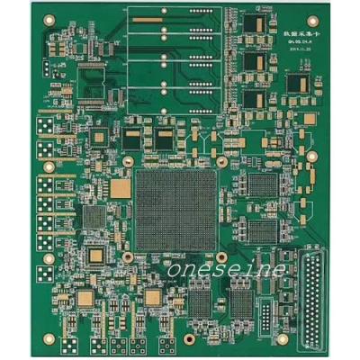
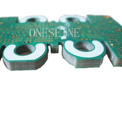
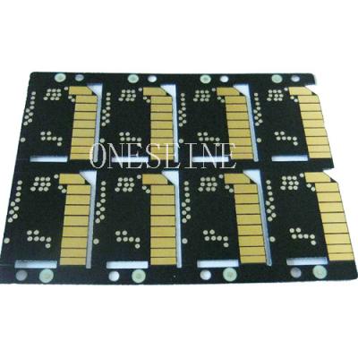
Fr1 Fr2 Fr3 Fr4 UL Specifications 94v0 0.5mm Fr PCB Circuits Boards
General information:
Material:fr4 94v0 |
Layer:2 |
Name: fr4 94vo double sided pcb printed circuit boards |
Surface finish: HASL lead free |
Copper thickness:17um |
PCB:Customized |
What does 94V-0 mean?
We often see the flame retardant plastic UL dash; 94 V0 class, what is the meaning? UL certification that the Underwriters Laboratories conducted a variety of certification in general. UL certification on the burning of plastic in two ways: one is that we usually see the most UL dash; 94 V0, V1, V2, V5, which is the vertical burning test method; the other is generally rare To the UL94 HB, which is the level of the test method. UL94 HB: Horizontal Burning This plastic burns slowly but does not extinguish itself. This type is the lowest level of UL, often with vertical V0, V1 or V2 approach does not work when using this method. UL94 V0: Vertical Flame UL Flammability Classification system is as follows: UL94 V0 Assessment Method: After the flame is removed from the flame after the sample can quickly self-extinguish to a certain time gap without burning the melt dripping (That is, the burning melt drips on a one-foot cotton pad underneath the test sample and does not ignite the cotton). UL94 V1 evaluation method and V0 similar, but it requires a longer self-extinguishing time. This test allowed the melt to drip onto the cotton pad, but not the cotton. The UL94 V2 is the same as the V1 except that it allows the burning droplets to ignite cotton below one foot. UL94 V5 is the most stringent detection method, it relates to the actual plastic products in the flame life. The test required a flame length of 5 in. Five burns were applied to the test specimen. No droplet dripping was allowed during the test. The test sample was not allowed to distort significantly and no burnt holes.
FR4 94v0 circuit boards assembly:
Please contact us for accurate price
FR4 Material Types
FR-4 has many different variations depending on the thickness of the material and chemical properties, such as the standard FR-4 and G10. The following list shows some common designations for FR4 PCB materials.
Standard FR4: This is the most common type of FR4. It provides good mechanical and moisture resistance, with heat resistance of about 140℃ to 150℃.
FR4 With High Tg: FR4 with high Tg is suitable for applications requiring high thermal cycling and temperatures greater than 150℃. Standard FR4 is limited to around 150℃, while FR4 with high Tg can withstand much higher temperatures.
FR4 With High CTI: FR4 with high CTI (Chemical Thermal Interaction) has better thermal conductivity than regular FR4 material. It has a comparative tracking index higher than 600 Volts.
FR4 without copper laminate: FR4 without copper laminate is a non-conductive material with excellent mechanical strength. It is mainly suitable for insulating boards and board supports.
FR4 G10: FR-4 G10 is a solid core material with excellent mechanical properties, high thermal shock resistance, excellent dielectric properties, and good electrical insulation properties.
The requirements of high frequency pcb material:
(1) the dielectric constant (Dk) must be very stable
(2) Dielectric loss (Df) must be small, which mainly affects the quality of signal transmission, the smaller the dielectric loss so that the signal loss is also smaller.
(3) and copper foil thermal expansion coefficient as far as possible, because inconsistencies in the change in the cold and heat caused by copper foil separation.
(4) low water absorption, high water absorption will be affected in the damp when the dielectric constant and dielectric loss.
(5) Other heat resistance, chemical resistance, impact strength, peel strength, etc. must also be good.
What Is FR4 PCB Material?
FR-4 is a high-strength, high-resistant, glass-reinforced epoxy laminate material used to fabricate printed circuit boards (PCBs). The National Electrical Manufacturers Association (NEMA) defines it as a standard for glass-reinforced epoxy laminates.
The FR stands for flame retardant, and the number 4 differentiates this type of laminate from other similar materials. This particular laminate has woven glass-reinforced epoxy resin.
FR-4 PCB refers to the board manufactured with adjacent laminate material. This material is incorporated in double-sided, single-sided, and multi-layered boards.
ONESEINE'S STANDARD FR-4 MATERIAL PROPERTIES
High Glass Transition Temperature (Tg) (150Tg or 170Tg)
High Decomposition Temperature (Td) (> 345º C)
Low Coefficient of Thermal Expansion (CTE) ((2.5%-3.8%)
Dielectric Constant (@1 GHz): 4.25-4.55
Dissipation Factor (@ 1 GHz): 0.016
UL rated (94V-0, CTI = 3 minimum)
Compatible with standard and lead-free assembly.
Laminate thickness available from 0.005” to 0.125”
Pre-preg thicknesses available (approximate after lamination):
(1080 glass style) 0.0022”
(2116 glass style) 0.0042”
(7628 glass style) 0.0075”
FR4 PCB Applications:
FR-4 is a common material for printed circuit boards (PCBs). A thin layer of copper foil is typically laminated to one or both sides of an FR-4 glass epoxy panel. These are commonly referred to as copper clad laminates. The copper thickness or copper weight can vary and so is specified separately.
FR-4 is also used in the construction of relays, switches, standoffs, busbars, washers, arc shields, transformers and screw terminal strips.
Here are some key aspects related to the thermal stability of FR4 PCBs:
The thermal stability of FR4 PCBs refers to their ability to withstand and operate under different temperature conditions without experiencing significant degradation or performance issues.
FR4 PCBs are designed to have good thermal stability, meaning they can handle a wide temperature range without warping, delaminating, or suffering from electrical or mechanical failures.
Glass Transition Temperature (Tg): Tg is an important parameter that characterizes the thermal stability of FR4. It represents the temperature at which the epoxy resin in the FR4 substrate undergoes a transition from a rigid state to a more flexible or rubbery state. FR4 PCBs typically have a Tg value around 130-180°C, which means they can withstand elevated temperatures without significant changes in their mechanical properties.
Coefficient of Thermal Expansion (CTE): CTE is a measure of how much a material expands or contracts with changes in temperature. FR4 PCBs have a relatively low CTE, which ensures that they can withstand thermal cycling without excessive stress or strain on the components and solder joints. The typical CTE range for FR4 is around 12-18 ppm/°C.
Thermal Conductivity: FR4 itself is not highly thermally conductive, which means it is not an excellent heat conductor. However, it still provides adequate heat dissipation for most electronic applications. To enhance the thermal performance of FR4 PCBs, additional measures can be taken, such as incorporating thermal vias or using additional heat sinks or thermal pads in critical areas to improve heat transfer.
Soldering and Reflow Processes: FR4 PCBs are compatible with standard soldering and reflow processes commonly used in electronic assembly. They can withstand the elevated temperatures involved in soldering without significant damage or dimensional changes.
It's important to note that while FR4 PCBs have good thermal stability, they still have limits. Extreme temperature conditions, such as very high temperatures or rapid temperature changes, can potentially cause stress, delamination, or other issues. Therefore, it's important to consider the specific operating environment and choose appropriate materials and design considerations accordingly.