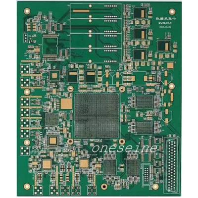
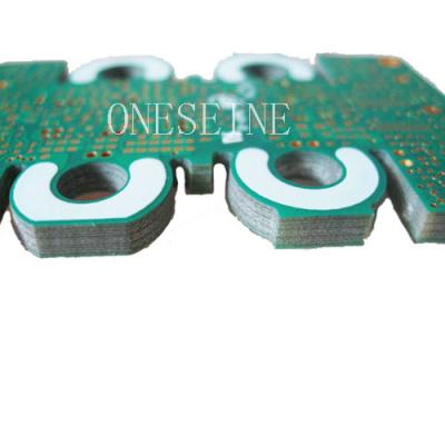
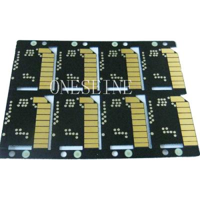
HDI Green Double Sided PCB Board Fabrication Isola FR408 FR408HR
Specification:
Base Material: isola FR408 FR408HR |
Layer:2 |
Thickness: 0.8MM |
Copper weight:2OZ |
Surface finish: ENIG |
Isola FR408 printed circuit board:
Double-sided pcb have one layer dielectric layer in the middle, both sides are traces layer. Multilayer PCB is a multilayer traces layer, a dielectric layer between each 2 layer, a dielectric layer may be made very thin layers . Multilayer circuit board having at least three conductive layers, wherein the outer surface 2layers, while the remaining one was synthesized in the insulating plate. Electrical connection between them is usually done by plated through holes in the circuit board on the implementation of the cross section
Isola FR408 is a high-performance FR-4 epoxy laminate and prepreg system designed for advanced circuitry applications.
Its low dielectric constant (Dk) and low dissipation factor (Df) make it an ideal candidate for broadband circuit designs requiring faster signal speeds or improved signal integrity. FR408 is compatible with most FR-4 processes. This feature allows the use of FR408 without adding complexity to current fabrication techniques
This is the standard laminate used in our sector of the industry. We carry stocks of all the main variants. The standard thickness used is 1.6mm, but we also stock 0.8mm, 1.0mm, 1.2mm, 2.0mm, 2.4mm, and 3.2mm. The most common copper thickness is 35 microns or 1oz square foot but 70 microns 2 oz square Ft is regularly used for higher current applications.
Its closely related to FR5 which is the old high temperature version, but has now been replaced by the more common BT Epoxy type.
FR4 Data Sheet :
| Model | ER | Tanδ@ 1GHz | Cter (ppm/℃) | CTE (X,Y) (ppm/℃) |
FR4 | Normal | 4.6 | 0.030 | 17 |
|
FR4 | PCL370(FR4-HTG) | 4.3 | 0.0015 | 51 | 17 |
FR4 | 117 (FR4-HTG) | 4.4 | 0.013 |
| 17 |
Park Neclo | N4000-6-FC BC (FR4-HTG) | 4.1 | 0.0015 |
| 16 |
ONESEINE'S STANDARD FR-4 MATERIAL PROPERTIES
High Glass Transition Temperature (Tg) (150Tg or 170Tg)
High Decomposition Temperature (Td) (> 345º C)
Low Coefficient of Thermal Expansion (CTE) ((2.5%-3.8%)
Dielectric Constant (@1 GHz): 4.25-4.55
Dissipation Factor (@ 1 GHz): 0.016
UL rated (94V-0, CTI = 3 minimum)
Compatible with standard and lead-free assembly.
Laminate thickness available from 0.005” to 0.125”
Pre-preg thicknesses available (approximate after lamination):
(1080 glass style) 0.0022”
(2116 glass style) 0.0042”
(7628 glass style) 0.0075”
FR4 PCB Applications:
FR-4 is a common material for printed circuit boards (PCBs). A thin layer of copper foil is typically laminated to one or both sides of an FR-4 glass epoxy panel. These are commonly referred to as copper clad laminates. The copper thickness or copper weight can vary and so is specified separately.
FR-4 is also used in the construction of relays, switches, standoffs, busbars, washers, arc shields, transformers and screw terminal strips.
Here are some key aspects related to the thermal stability of FR4 PCBs:
The thermal stability of FR4 PCBs refers to their ability to withstand and operate under different temperature conditions without experiencing significant degradation or performance issues.
FR4 PCBs are designed to have good thermal stability, meaning they can handle a wide temperature range without warping, delaminating, or suffering from electrical or mechanical failures.
Glass Transition Temperature (Tg): Tg is an important parameter that characterizes the thermal stability of FR4. It represents the temperature at which the epoxy resin in the FR4 substrate undergoes a transition from a rigid state to a more flexible or rubbery state. FR4 PCBs typically have a Tg value around 130-180°C, which means they can withstand elevated temperatures without significant changes in their mechanical properties.
Coefficient of Thermal Expansion (CTE): CTE is a measure of how much a material expands or contracts with changes in temperature. FR4 PCBs have a relatively low CTE, which ensures that they can withstand thermal cycling without excessive stress or strain on the components and solder joints. The typical CTE range for FR4 is around 12-18 ppm/°C.
Thermal Conductivity: FR4 itself is not highly thermally conductive, which means it is not an excellent heat conductor. However, it still provides adequate heat dissipation for most electronic applications. To enhance the thermal performance of FR4 PCBs, additional measures can be taken, such as incorporating thermal vias or using additional heat sinks or thermal pads in critical areas to improve heat transfer.
Soldering and Reflow Processes: FR4 PCBs are compatible with standard soldering and reflow processes commonly used in electronic assembly. They can withstand the elevated temperatures involved in soldering without significant damage or dimensional changes.
It's important to note that while FR4 PCBs have good thermal stability, they still have limits. Extreme temperature conditions, such as very high temperatures or rapid temperature changes, can potentially cause stress, delamination, or other issues. Therefore, it's important to consider the specific operating environment and choose appropriate materials and design considerations accordingly.