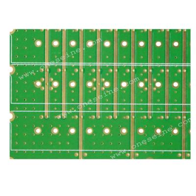
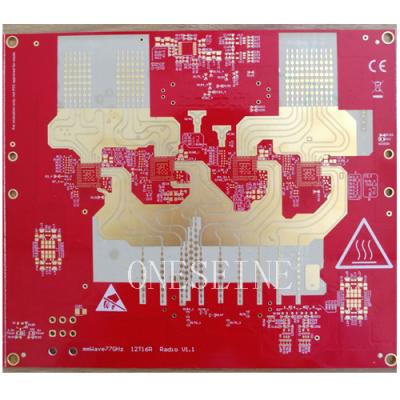
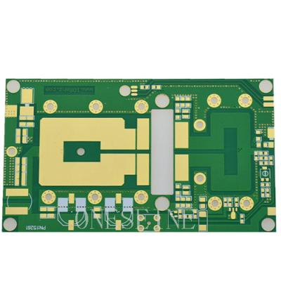
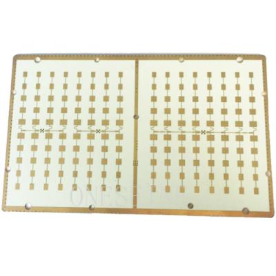
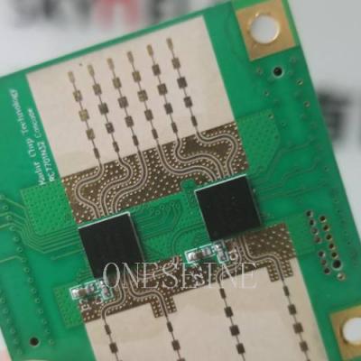
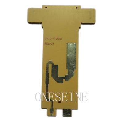
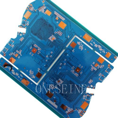
Taconic RF35A PTFE substrate microwave laminates PCB
Detailed Product Description
Layer: 3 |
Material: RF35A 0.6mm |
Board size: 14*12cm |
Surface finish: Immersion gold,ENIG |
Board thickness:0.8mm |
Copper thickness: 1OZ |
Min line width:5mil |
Name: High Frequency Taconic RF60TC / RF35TC PCB Boards |
Min hole: 0.2MM |
Delivery time: 5 days for sample(material in stock) ,please confirm with us the material is in stock or not |
Sufficient stock:
We have sufficient taconic material as follow:
TLY-5A TLY-5 TLY-3 HT1.5 TLX-0 TLX-9 TLX-8 TLX-7 TLX-6 TLC-27 TLE-95 TLC-30 TPG-30 TLG-30 RF-30 TSM-30 TLC-32 TPG32 TLG-32 TLG-34 TPG35 TLG-35 RF-35 RF-35A RF-35P RF-41 RF-43 RF-45 RF-60A CER-10
Brand | Model | Thickness(mm) | DK(ER) | DF |
TACONIC | TLX-8.TLX-9 | 0.508,0.762 | 2.45-2.65 | 0.0012 |
TLC-32 | 0.254,0.508,0.762 | 3.2 | 0.003 | |
TLY-5 | 0.254,0.508.0.8,1.52 | 2.2 | 0.0009 | |
RF-60A | 0.254.0.508.0.762 | 6.15 | 0.0028 | |
RF-10 | 0.254.0.508.0.64,1.52 | 10.2 | 0.0025 | |
RF-30A | 0.254.0.508.0.762 | 2.97 | 0.0013 | |
RF-35 | 0.25,0.5,0.76,1.52 | 3.5 | 0.0018 | |
TLA-35 | 0.8 | 3.5 | 0.0016 |
Taconic High Frequency Microwave / RF printed circuit boards
Taconic's Industrial Products Division produces PTFE and silicone coated fabrics, tapes and belts for a wide range of industrial applications. These durable coatings offer a host of benefits that make them ideal for demanding environments.
Taconic's Advanced Dielectric Division is a world leader in RF laminates, prepregs and high speed digital and flexible interconnect materials utilized in some of the most cutting-edge communication systems in the world.
Our service:taconic PCB fabrication,PTFE pcb prototype,High frequency PCB manufacturer,microwave pcb design,Taconic fabrication pcb, taconic PCB manufacturer, suppliers, factory, datasheet, buy, price, pcb, taconic substrate, taconic tly-5, taconic laminate, taconic , ptfe pcb
Taconic material:
The most popular Taconic model: Taconic TLY-5,Taconic TLX-8,Taconic TLX-9
Taconic RF-60,Taconic CER-10,Taconic TLA-35,Taconic RF35
Taconic pcb requirements from customer:
1,Please send price on your RF35 Taconic PCB Board Satellite Receiver 2 layer pcb High Frequency Microwave
2,we need PCBs with RF60TC and RF60TC material
3,Materials only TC350 from Arlon or RF35-TC from Taconic, thickness 30 mils, only top solder, no silk screen, immersion gold finish, qty 150 pcs
4,Please make sure ship the TLY-5 pcb boards within 8days,this is our basic requirements,thanks
Application:
Communications, power, instrumentation, computer networks, digital products, industrial control, scientific, educational, medical, aerospace and defense, and other high-tech fields.
Excellent mechanical & thermal properties,Low and stable Dk ,Dimensionally stable,Low moisture absorption
Tightly controlled DK,Low DF ,UL 94 VO rating,For low layer count ,microwave designs
Taconic material specification:
TLX offers reliability in a wide range of RF applications. This material is versatile due to its 2.45 - 2.65 DK range and available thicknesses and copper cladding. It is suitable for low layer count microwave designs.
TLX PTFE fiberglass laminates are ideal for use in radar systems, mobile communications, microwave test equipment, microwave transmission devices and RF components.
TLF-35 is an organic-ceramic laminate in Taconic’s family of product. It is based on woven glass reinforcement. TLF-35 is a result of Taconic’s expertise in both ceramic fill technology and in coated PTFE fiberglass.TLF-35 advanced is the best choice for low cost, high volume commercial microwave and radio frequency application. TLF-35 advanced has excellent peel strength for ½ounce and 1 ounce copper (even in comparison to standard epoxy materials), a critical aspect whenever rework is required.TLF-35 advanced is designed to offer superior high frequency performance. TLF-35’s ultra low moisture absorption rate and low dissipation factor minimize phase shift with frequency.
RF-10 copper clad laminates are composites of ceramic filled PTFE and woven fiberglass. RF-10 has the advantage of high dielectric constant and low dissipation factor. Thin woven fiberglass reinforcement is used to offer both low dielectric loss and improved rigidity for ease of handling and improved dimensional stability for multilayer circuits.
RF-10 laminates are engineered to provide a cost effective substrate with industry acceptable delivery times. RF-10 responds to a need in RF applications for size reduction.
RF-10 bonds well to smooth low profile copper. The low dissipation of RF-10 combined with the use of very smooth copper results in optimal insertion losses at higher frequency where skin effect losses play a substantial role.
RF-60A is an organic ceramic fiberglass reinforced laminate. This product’s unique composition results in low moisture absorption and uniform electrical properties.
RF-60A’s woven fiberglass reinforcement assures excellent dimensional stability and enhanced flexural strength as well as low Z-axis expansion which allows for plated-through-hole reliability in extreme thermal environments. RF-60A also exhibits exceptional interlaminar bond strength and solder resistance.
Taconic is a world leader in RF laminates and high speed digital materials, offering a wide range of high frequency laminates and prepregs. These advanced materials are used in the fabrication of antennas, multilayer RF and high speed digital boards, interconnections and devices.
RF-30Aisanorganic-ceramiclaminateinTaconic’sfamilyofRFsubstrates.Itisbasedonwovenglassreinforcement.RF-30AisaresultofTaconic’sexpertiseinbothceramicfillerandPTFEcoatingtechnology..
RF-30Aisthebestchoiceforlowcost,highvolumecommercialmicrowaveandradiofrequencyapplication..
High frequency PCB range:
Frequency Range: High-frequency PCBs are designed to operate in frequency ranges typically starting from a few megahertz (MHz) and extending into the gigahertz (GHz) and terahertz (THz) ranges. These PCBs are commonly used in applications such as wireless communication systems (e.g., cellular networks, Wi-Fi, Bluetooth), radar systems, satellite communication, and high-speed data transmission.
Signal Loss and Dispersion: At high frequencies, signal loss and dispersion become significant concerns. High-frequency PCBs employ techniques to minimize these effects, such as using low-loss dielectric materials, controlled impedance routing, and minimizing the length and number of vias.
PCB Stackup: The stackup configuration of a high-frequency PCB is carefully designed to address signal integrity requirements. It typically consists of multiple layers of copper traces, dielectric materials, and ground planes. The arrangement of these layers is optimized to control impedance, minimize crosstalk, and provide shielding.
RF Connectors: High-frequency PCBs often incorporate specialized RF connectors to ensure proper signal transmission and minimize losses. These connectors are designed to maintain consistent impedance and minimize reflections.
Electromagnetic Compatibility (EMC): High-frequency PCBs must comply with electromagnetic compatibility standards to prevent interference with other electronic devices and to avoid susceptibility to external interference. Proper grounding, shielding, and filtering techniques are employed to address EMC requirements.
Simulation and Analysis: Designing high-frequency PCBs often involves simulation and analysis using specialized software tools. These tools allow designers to assess signal integrity, impedance matching, and electromagnetic behavior before fabrication, helping to optimize the PCB design for high-frequency performance.
Fabrication Challenges: Fabricating high-frequency PCBs can be more challenging compared to standard PCBs. The use of specialized materials, controlled impedance requirements, and tight tolerances require advanced fabrication techniques such as accurate etching, controlled dielectric thickness, and precise drilling and plating processes.
Testing and Validation: High-frequency PCBs undergo rigorous testing and validation to ensure their performance meets the desired specifications. This includes impedance testing, signal integrity analysis, insertion loss measurement, and other RF and microwave tests.
It's important to note that the design and manufacturing of high-frequency PCBs are specialized areas requiring expertise in RF and microwave engineering, PCB layout, and fabrication processes. Working with experienced professionals and consulting relevant design guidelines and standards is crucial to ensure reliable performance at high frequencies.
High frequency PCB description:
High frequency PCB material in stock:
Brand | Model | Thickness(mm) | DK(ER) |
Rogers | RO4003C | 0.203mm,0.305mm,0.406mm,0.508mm,0.813mm,1.524mm | 3.38 ± 0.05 |
RO4350B | 0.101mm,0.168mm,0.254mm,0.338mm,0.422mm,0.508mm,0.762mm,1.524mm | 3.48 ± 0.05 | |
RO4360G2 | 0.203mm,0.305mm,0.406mm,0.508mm,0.610mm,0.813mm,1.524mm | 6.15 ± 0.15 | |
RO4835 | 0.168mm,0.254mm,0.338mm,0.422mm,0.508mm,0.591mm, 0.676mm,0.762mm,1.524mm | 3.48 ± 0.05 | |
RT5870 | 0.127mm,0.787mm,0.254mm,1.575mm,0.381mm,3.175mm,0.508mm | 2.33 2.33 ± 0.02 | |
RT5880 | 0.127mm,0.787mm,0.254mm,1.575mm,0.381mm,3.175mm,0.508mm | 2.20 2.20 ± 0.02 | |
RO3003 | 0.13mm,0.25mm,0.50mm,0.75mm,1.52mm | 3.00 ±0.04 | |
RO3010 | 0.13mm,0.25mm,0.64mm,1.28mm | 10.2 ± 0.30 | |
RO3006 | 0.13mm,0.25mm,0.64mm,1.28mm | 6.15 ± 0.15 | |
RO3203 | 0.25mm,0.50mm,0.75mm,1.52mm | 3.02±0.04 | |
RO3210 | 0.64mm,1.28mm | 10.2±0.50 | |
RO3206 | 0.64mm,1.28mm | 6.15±0.15 | |
R03035 | 0.13mm,0.25mm,0.50mm,0.75mm,1.52mm | 3.50 ± 0.05 | |
RT6002 | 0.127mm,0.254mm,0.508mm,0.762mm,1.524mm,3.048mm | 2.94 ± 0.04 | |
RT6006 | 0.127mm,0.254mm,0.635mm,1.27mm,1.90mm,2.50mm | 6.15± 0.15 | |
RT6010 | 0.127mm,0.254mm,0.635mm,1.27mm,1.90mm,2.50mm | 10.2 ± 0.25 | |
TACONIC | TLX-8.TLX-9 | 0.508. 0.762 | 2.45-2.65 |
TLC-32 | 0.254,0.508,0.762 | 3.35 | |
TLY-5 | 0.254,0.508.0.8, | 2.2 | |
RF-60A | 0.254.0.508.0.762 | 6.15 | |
CER-10 | 0.254.0.508.0.762 | 10 | |
RF-30 | 0.254.0.508.0.762 | 3 | |
TLA-35 | 0.8 | 3.2 | |
ARLON | AD255C06099C | 1.5 | 2.55 |
MCG0300CG | 0.8 | 3.7 | |
AD0300C | 0.8 | 3 | |
AD255C03099C | 0.8 | 2.55 | |
AD255C04099C | 1 | 2.55 | |
DLC220 | 1 | 2.2 |