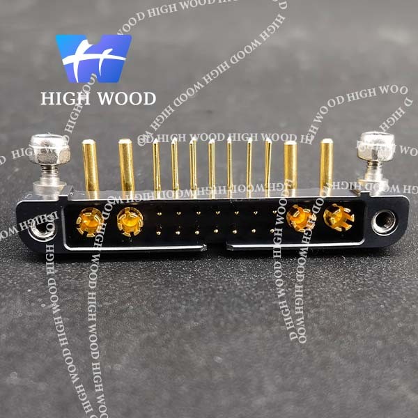
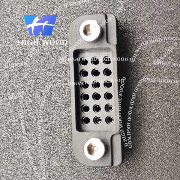
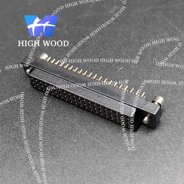
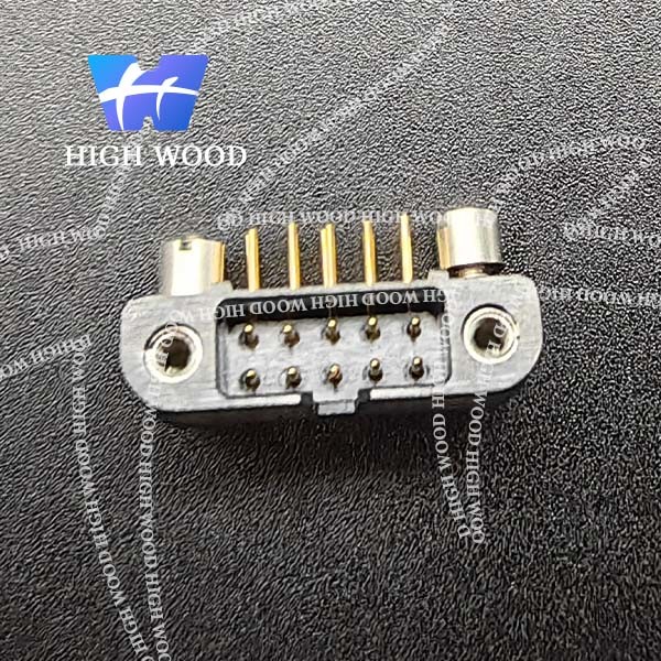
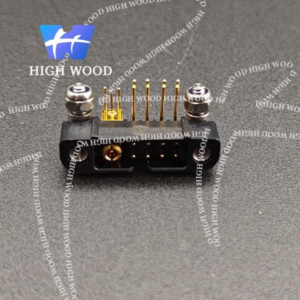
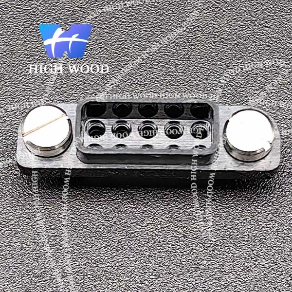
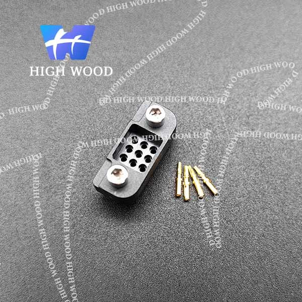
HW-E222Y36E50
Part numbering | |||||||
E Series 2 rows | Gender | LF contact type | LF contact nbr | Fixing | Visual | Mating | Visual |
E22 |
1 Male |
Y/YL Straight Thru hole 3mm/4.5mm |
04 to 60 | E10/E10L Male Straight Guiding | ![]() | E60/E61 | |
E50/E50L Female Straight Jackscrew | E01/E02 | ||||||
E60/E60L Female Straight Guiding | E10/E11 | ||||||
2 Female |
T Straight SMT | ||||||
E01 Jackscrew for Harness |
E50/E51 | ||||||
E02 Captive Screw for Harness |
Housings:
→ STRAIGHT ON PCB
Product showing.
Performance
MIL 83513-G Requirements | EMM Results |
Electrical performance requirements | |
Dielectric withstanding voltage sea level EIA-364-20C (Performances between contacts) Dielectric withstanding voltage @sea level: 600 V RMS. Connectors shall show no evidence of breakdown or flashover | Dielectric withstanding voltage: 750 V RMS Breakdown voltage: 1000 V RMS Rated voltage: 250 V RMS |
Dielectric withstanding voltage high altitude EIA-364-20C (Performances between contacts) Dielectric withstanding voltage @70 000 k: 150V RMS. Connectors shall show no evidence of breakdown or flashover | Dielectric withstanding voltage @30 000 ft: 540 V RMS Dielectric withstanding voltage @70 000 ft: 480 V RMS Dielectric withstanding voltage @100 000 ft: 465V RMS |
Insulation resistance EIA 364-21C Shall not be less than 5 GΩ aker temperature cycling and humidity | > 2000 GΩ@ 500V |
Contact resistance EIA 364-06C For AWG 24, contact resistance shall be less than 24 mΩ |
Less than 8 mΩ |
Low level contact resistance EIA 364-06C For AWG 24, shall be less than 25 mΩ |
Less than 9 mΩ |
Magnetic permeability ASTM A342/A342M Shall not exceed 2 gamma |
Less than 2 gamma |
Contact current capability (derating) IEC 60512-5-2 Test 5b For PCB connectors, contacts shall be capable of carrying 3.0 A in continuous duty operation from -55°C to 150°C For contacts on cable, derating is depending on the cable. Refer to test results |
For 30 pins: Configuration Y/Y: 3,4A @25°C and 2,5A @85°C Confiiguration Y/V: 3,9A @25°C and 2,5A @85°C |
Mechanical features | |
Contact engagement and separation forces EIA 364-37B For AWG24, contact engaging shall not exceed 1,67 N and contact separation shall be 0.14N min | Engagement force: 1N max Separation force: 0.15 N |
Connector mating and unmating forces EIA 364-13D Shall not exceed a value equal to 2,78 N times the number of contacts | Mating Force: 1.7N max Unmating Force: 0.1N min |
Durability MIL-DTL-83513G §4,5,16 Counterpart connectors shall show no mechanical or electrical defects detrimental to the operation of the connector aker 500 cycles of mating and unmating |
Qualified |
Crimp tensile strength EIA 364-08B IPC-WHMA-A-620B Requested: AWG24 > 35.6 N / AWG26 > 22.3 N / AWG28 > 13.4 N AWG30 > 6.7 N NASA-STD 8739.4 Requested AWG24>22.3N / AWG 26>13.5N |
AWG 24: 49.98 N min AWG 26: 36.64 N min AWG 28: 16.90 N min AWG 30: 11.30 N min |