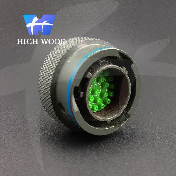
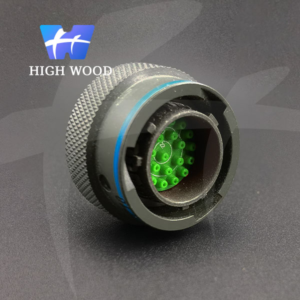
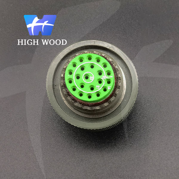
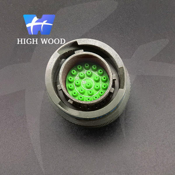
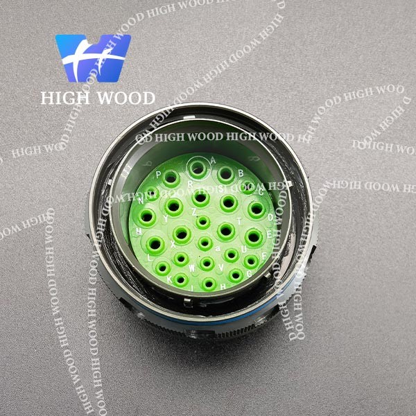
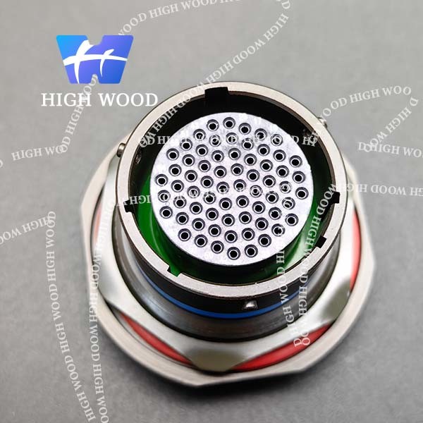
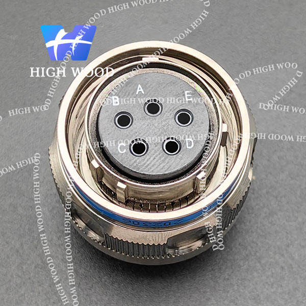
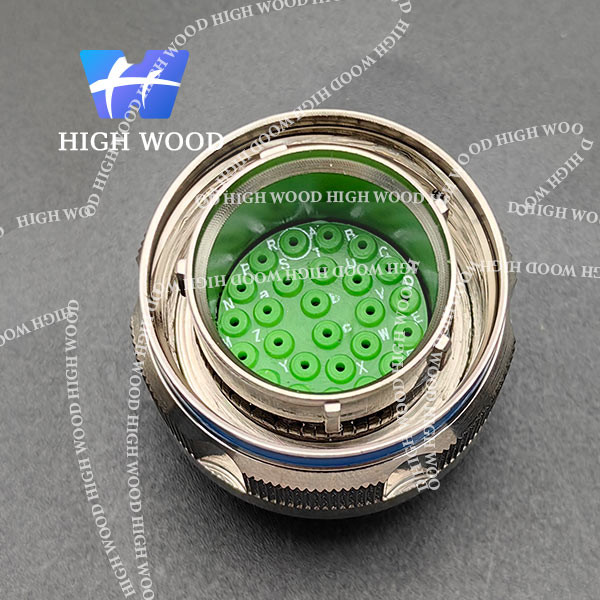
D38999/MS27484T12B35P
This series of round connectors, compliant with MIL-DTL-38999 Ⅱ series requirements, adopt card button quick connection, with an anti- loose mechanism, featuring small size, light weight, high-density contacts EMI/RFI shielding, removable crimp contacts, and anti oblique-mating;
This product has a fireproof shell, a variety of coatings, and vibration performance of high strength under high temperature, suitable for use in harsh sandstorm and damp circumstances.
With quick connection, anti- loose mechanism, EMI/RFI shielding, interface sealing, anti oblique-mating design, the material of shell is optional in aluminum-alloy, naval brass, stainless steel or composite.
How to order:
MS | 27472 | T | 14 | F | 35 | P | N |
Basic series | |||||||
Type of connector 27473 = Plug 27484 = Shielded plug 27472 = Wall mounting square receptacle, front 27497 = Wall mounting square receptacle, rear 27513 = Box square receptacle, front 27508 = Box square receptacle, rear 27474 = Jam nut receptacle | |||||||
Shell T = With thread and accessory E = Without thread or accessory | |||||||
Shell size 08, 10, 12, 14, 16, 18, 20, 22, 24 | |||||||
Finish B = Olive green cadmium plating F1 = Spray desertification nickel C = Black anodized C3 = Black zinc nickel alloy (black chromium) E = Passivated stainless steel C1 = Oxide olive green F = Electroless nickel plating C2 = Oxide black | |||||||
Contact layout (See below) | |||||||
Type of contact P=Crimp pin PC=Short PCB pin H= Crimp pin HC=Short PCB pin S= Crimp socket SC=Short PCB socket J= Crimp socket JC=Short PCB socket PH=Solder pin PL=Long PCB pin HH= Solder pin PL=Long PCB pin SH= Solder socket SL= Long PCB socket JH= Solder socket SL= Long PCB socket | |||||||
Orientation N = Normal A, B, C, D = Alternative |
Product pictures:
Crimp contacts:
Contact ID | Diameter (mm) | Pin color | Socket color | crimp barrel inner diameter (mm) | crimp barrel external diameter (mm) | Conductor section (mm2) | American standard cable AWG | Wire insulation outside diameter (mm) | Unloading tools code |
22D# | 0.76 | orange-blue -black | orange-green -yellow | 0.85 | 1.20 | 0.08 0.125 0.2 0.3 | 28 26 24 22 | 0.76 ∽1.37 | M81969/ 14-01 |
20# | 1.00 | orange-blue -orange | orange-green -purple | 1.17 | 1.78 | 0.2 0.3 0.5 | 24 22 20 | 1.02 ∽2.11 | M81969/ 14- 10 |
16# | 1.60 | orange-blue -yellow | orange-green -gray | 1.68 | 2.62 | 0.5 0.8 1.0 1.2 | 20 18 16 | 1.65 ∽2.77 | M81969/ 14-03 |
12# | 2.40 | orange-blue -green | orange-green -white | 2.49 | 3.84 | 2.0 3.0 | 14 12 | 2.46 ∽3.61 | M81969/ 14-04 |
Electrical
Contact resistance and current rating:
Contact ID | Diameter (mm) | Resistance (mΩ) | Current (A) |
22D# | Φ 0.76 | ≤ 12 | 5.0 |
20# | Φ 1.00 | ≤ 5.0 | 7.5 |
16# | Φ 1.60 | ≤ 2.5 | 13.0 |
12# | Φ 2.40 | ≤ 1.5 | 23.0 |
EMI shielding:
100MHz~1GHz: minimum attenuation45 dB
Withstanding voltage (V):
Service rating | M | I | II |
Sea level | 1300 | 1800 | 2300 |
21000m | 800 | 1000 | 1000 |
Insulation resistance:
Normal ≥ 5000MΩ, damp heat ≥ 100MΩ
Electrical continuity between shells:
Class B≤ 2.5mΩ, Class E ≤ 2.5mΩ, Class F≤ 1.0mΩ
Contact: Copper alloy with gold plated, pressure type, welding type
Endurance: 500 cycles
Vibration:
Random vibration: at frequency: 100 ~ 1000 Hz, density of power chart: 1 G2/Hz
Shock: at 3ms half sinusoid, peak value of acceleration: 300 g
Contact layout: