8 Inch 1024x768 Dots Color TFT LCD Modules/HX8282A+HX8695/TFT-H080A2XGTHX3N40
Product parameters
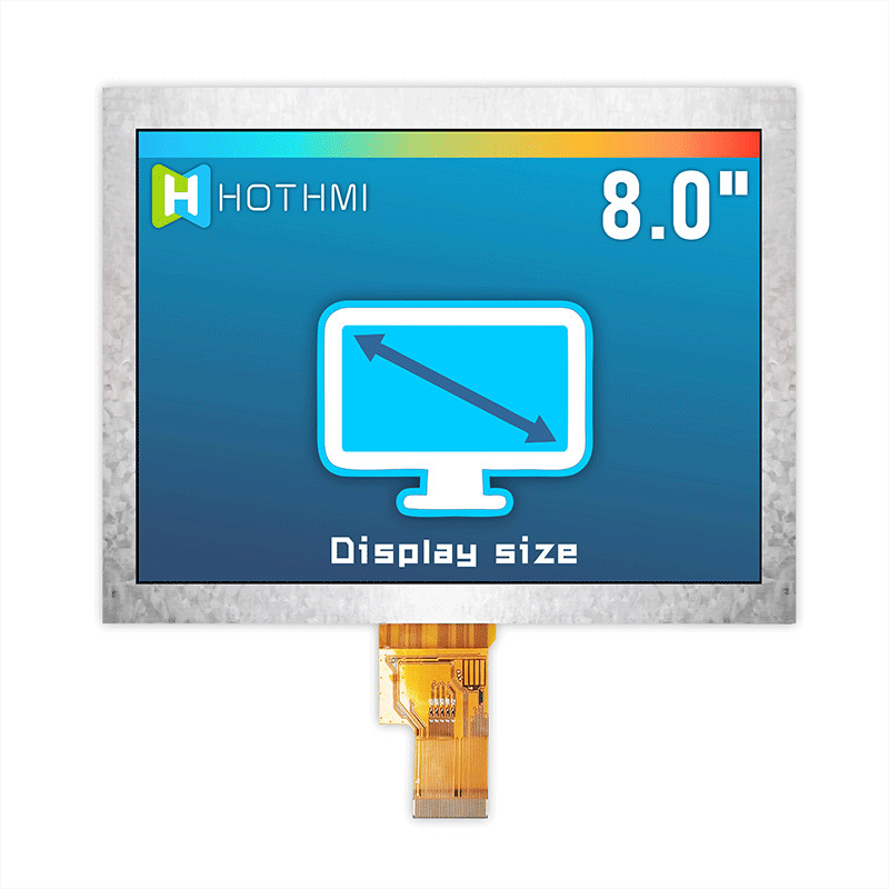
Effective size mm - 162.05x121.54
Perspective - 12H
Backlight brightness - 300cd/m2
Connection method PIN number - FPC-40PIN
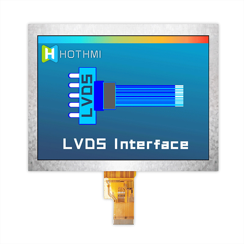
Interface method - LVDS
Operating temperature - (-20~70℃)
Supply Voltage - 3.3V
General Feature
Item | Standard Value | Unit |
Display Size | 8.0” | -- |
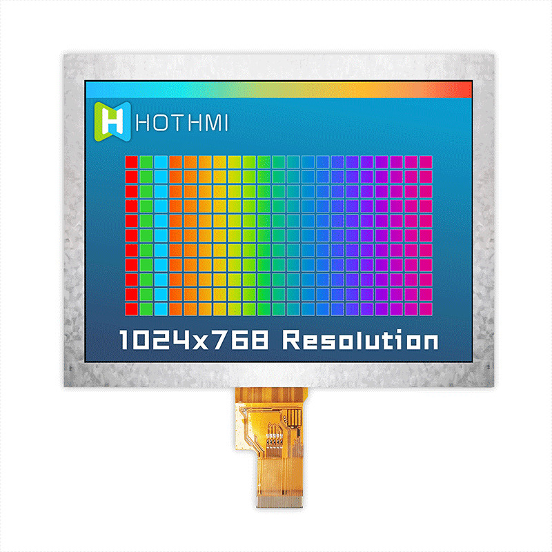
Number of Pixels | 1024(H)x3(RGB)*768(V) | -- |
Active Area | 162.05(H) * 121.54(V) | mm |
Outline Dimension | 174.50(H) × 135.70(V) × 3.00(D) | mm |
Viewing Direction | 12 O'clock | - |
Interface | LVDS 4L | - |
Panel Driver IC | HX8282A+HX8695_B01 | - |
Panel Driver Condition | VCI=3.3V | V |
Backlight | White LED | - |
Touch Panel | Without Touch Panel | - |
Cap Touch Driver IC | - - - | - |
Cap Touch Driver Condition | - - - | V |
Operation Temperature | -20~70 | ℃ |
Storage Temperature | -30~80 | ℃ |
Pin Description
Pin NO. | Symbol | Description |
1 | VCOM | TFT Common Electrode Voltage |
2,3 | VDD | Analog Power |
4 | NC | Disconnect pin |
5 | RESX | Global reset pin.Active low to enter Reset State. Suggest to connecting with an RC reset circuit for stability. |
6 |
STBYB | Standby mode control. Normally pull High. When STB=H, all the functions are on. (Default pulls high). When STB=L, TCON and source driver are off and all output are High-z. |
7 | GND | Ground |
8 | D0N | Negative LVDS differential data inputs |
9 | D0P | Positive LVDS differential data inputs |
10 | GND | Ground |
11 | D1N | Negative LVDS differential data inputs |
12 | D1P | Positive LVDS differential data inputs |
13 | GND | Ground |
14 | D2N | Negative LVDS differential data inputs |
15 | D2P | Positive LVDS differential data inputs |
16 | GND | Ground |
17 | DCKN | Negative LVDS differential clock inputs |
18 | DCKP | Positive LVDS differential clock inputs |
19 | GND | Ground |
20 | D3N | Negative LVDS differential data inputs |
21 | D3P | Positive LVDS differential data inputs |
22 | GND | Ground |
23-24 | NC | Disconnect pin |
25 | GND | Ground |
26 | NC | Disconnect pin |
27 |
DIMO | Backlight dimmer signal for external controller. DIMO=H, Logical control signal to turn on external backlight controller. DIMO=L, Turn off external backlight controller. |
28 | HSD | 6-bit/8-bit input select. HSD= “L”, 8-bit; HSD= ‘ H ” , 6-bit |
29 | AVDD | Power supply for analog circuits |
30 | GND | Ground |
31,32 | LED_K | LED Cathode |
33 | L/R | Source Right or Left sequence control. Normally pull high. SHLR = “L”, shift left; SHLR = ‘ H ” , shift right |
34 |
U/D | Gate Up or Down scan control. Normally pull low. UPDN = “L”,From top to bottom; UPDN = “H”, From bottom to top . |
35 | VGL | Power supply for drive output Low |
36 |
CABCEN1 | CABC H/W enable pin. Normally pull low. When CABC_EN=”00”, CABC OFF. (Default mode) When CABC_EN=”01”, User interface Image. When CABC_EN=”10”, Still Picture. When CABC_EN=”11”, Moving Image. |
37 | CABCEN0 | |
38 | VGH | Power supply for drive output High |
39,40 | LED_A | LED Anode |