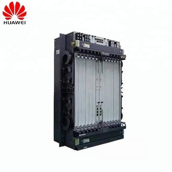
H801CITD Board
The H801CITD board is a combo interface transfer board. It provides the input and output clock source for the system and supports functions such as input and output of alarm digital parameters.
NOTE:
As shown in , the H801CITD board has the following changes after an upgrade from Ver.A to Ver.B:
Ports are adjusted by 180 degrees.
An ejector lever is added, facilitating board insertion and removal.
Feature and Specifications
The H801CITD board supports the following functions:
Seven inputs of alarm digital parameters and one output of digital controlling parameters
External monitoring Ethernet port to transparently transmit monitored data
When configured with the BITSB clock daughter board, the CITD board also provides the following functions:
Two inputs of 2 Mbit/s or 2 MHz BITS clock signals
Two inputs of 1 PPS+TOD time signals(supported in V800R013C10 and later versions)
One output of 2 Mbit/s or 2 MHz clock signals
One output of 1PPS time signals (supported in V800R013C10 and later versions)
Parameters
Power Consumption and Maximum Frame Size of Boards
You can query power consumption, maximum frame size, and normal operating temperature of all boards.
lists the power consumption and maximum frame size of boards. "-" indicates N/A.
The operating temperature of all the boards is -40°C to +65°C. The lowest board startup temperature is -25°C.
NOTE:
The power consumption of the board is tested in the following conditions:
Working voltage: -53.5 V DC.
Ambient temperature: 25 °C.
Static power consumption: All ports do not carry any loads. Specifically, users under POTS ports hang up phones, xDSL ports are deactivated, and optical modules are not installed on optical ports
Maximum power consumption: All ports fully carry loads. However, only 25% users under POTS ports concurrently pick up phones and the feeding current is 20 mA.
The board power consumption slightly varies with the power module configured for the board and discreteness of components.
Table 1 Power consumption and maximum frame size of boards
Board | Power Consumption | Maximum Frame Size |
Universal interface board (GPIO) | ||
H801CITD | Static: 3.64 W Maximum: 4.55 W | - |
The clock module provides clock signals for each functional module of the board.
Table 2 Pin assignments of the BITS/TOD IN1 port
Port | Pin | Signal | Remarks |
1 | BITS1_IN_B | Input B of channel 1 BITS clock signals | |
2 | BITS1_IN_A | Input A of channel 1 BITS clock signals | |
3 | PPS1_IN- | Negative polarity of channel 1 PPS time signals | |
4 | TOD1_IN- | Negative polarity of channel 1 TOD time signals | |
5 | TOD1_IN+ | Positive polarity of channel 1 TOD time signals | |
6 | PPS1_IN+ | Positive polarity of channel 1 PPS time signals | |
7 | - | - | |
8 | GND | Grounding |