PE4259 63 RF Switch IC SPDT Low IL Reflective 50 RF Switch
The PE4259 UltraCMOS® RF switch is designed to cover a broad range of applications from 10 MHz through 3000 MHz. This reflective switch integrates on-board CMOS control logic with a low voltage CMOS-compatible control interface, and can be controlled using either single-pin or complementary control inputs. Using a nominal +3-volt power supply voltage, a typical input 1dB compression point of +33.5 dBm can be achieved. The PE4259 is manufactured on Peregrine’s UltraCMOS process, a patented variation of siliconon-insulator (SOI) technology on a sapphire substrate, offering the performance of GaAs with the economy and integration of conventional CMOS
PE4259 Features
Single-pin or complementary CMOS
logic control inputs
Low insertion loss:
0.35 dB @ 1000 MHz
0.5 dB @ 2000 MHz
Isolation of 30 dB @ 1000 MHz
High ESD tolerance of 2 kV HBM
Typical input 1 dB compression point
of +33.5 dBm
1.8V minimum power supply voltage
Ultra-small SC-70 package
Control Logic Input The PE4259 is a versatile RF CMOS switch that supports two operating control modes; single-pin control mode and complementary-pin control mode. Single-pin control mode enables the switch to operate with a single control pin (pin 4) supporting a +3-volt CMOS logic input, and requires a dedicated +3-volt power supply connection on pin 6 (VDD). This mode of operation reduces the number of control lines required and simplifies the switch control interface typically derived from a CMOS Processor I/O port. Complementary-pin control mode allows the switch to operate using complementary control pins CTRL and CTRL (pins 4 and 6), that can be directly driven by +3-volt CMOS logic or a suitable Processor I/O port. This enables the PE4259 to be used as a potential alternate source for SPDT RF switch products used in positive control voltage mode and operating within the PE4259 operating limits.
Evaluation Kit The SPDT switch EK Board was designed to ease customer evaluation of Peregrine’s PE4259. The RF common port is connected through a 50Ω transmission line via the top SMA connector, J1. RF1 and RF2 are connected through 50Ω transmission lines via SMA connectors J2 and J3, respectively. A through 50Ω transmission is available via SMA connectors J4 and J5. This transmission line can be used to estimate the loss of the PCB over the environmental conditions being evaluated. The board is constructed of a two metal layer FR4 material with a total thickness of 0.031”. The bottom layer provides ground for the RF transmission lines. The transmission lines were designed using a coplanar waveguide with ground plane model using a trace width of 0.0476”, trace gaps of 0.030”, dielectric thickness of 0.028”, metal thickness of 0.0021” and εr of 4.4. J6 and J7 provide a means for controlling DC and digital inputs to the device. J6-1 is connected to the device VDD or CTRL input. J7-1 is connected to the device CTRL input
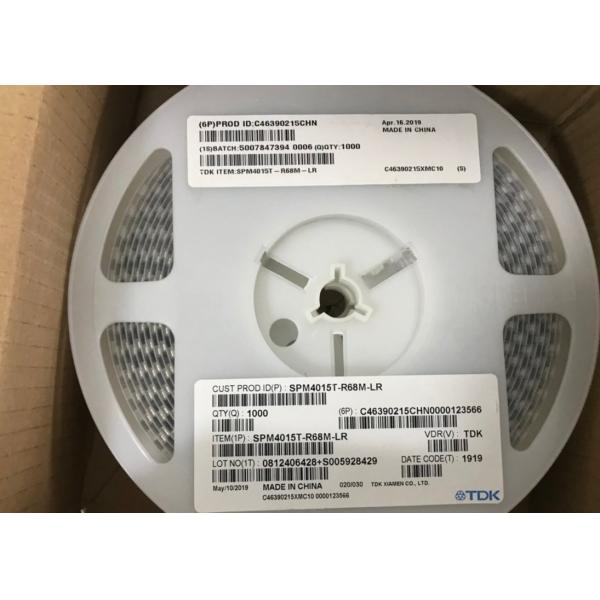
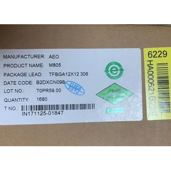
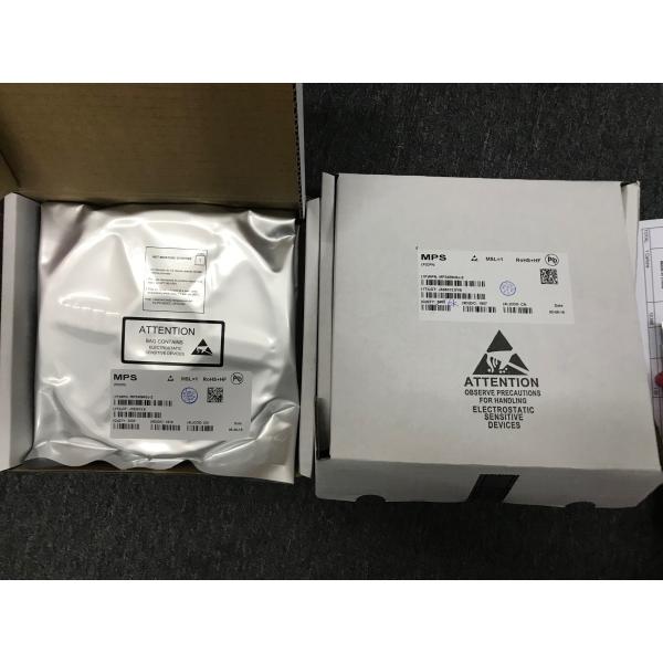
Q1. What is your terms of packing?
A: Generally, we pack our goods in neutral white boxes and brown cartons.
If you have legally registered patent, we can pack the goods in your branded boxes after getting your authorization letters.
Q2. What is your MOQ?
A: We provide you small MOQ for each item, it depends your specific order!
Q3. Do you test or check all your goods before delivery?
A: Yes, we have 100% test and check all goods before delivery.
Q4: How do you make our business long-term and good relationship?
We keep good quality and competitive price to ensure our customers benefit ;
We respect every customer as our friend and we sincerely do business and make friends with them,It's not something that can be replaced.
Q5: How to contact us?
A: Send your inquiry details in the below,Click "Send"Now!!!
Shenzhen Hongxinwei Technology Co., Ltd
To adopt new technology,to produce products of quality,to offer high-class service.
Improve the management system continuously to meet customer requirement for high-quality products and services.
Why choose us?