Product Introduction
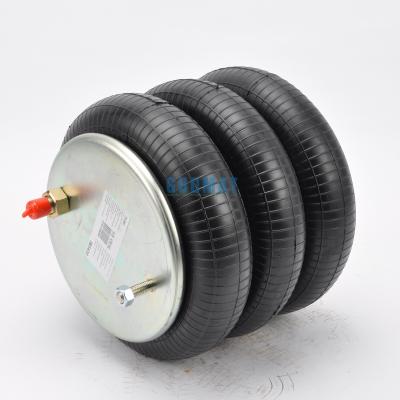
Air springs are single-acting pneumatic actuators made of reinforced elastic material. They are connected to metal covers at both ends with mounting holes and air inlets, making them easy to fix and use. Air bags are divided into three main variants according to the design: single blade, double blade and triple blade structure to meet different application needs. AIRSUSTECH air spring assemblies are extremely effective vibration isolation devices that can be applied to various types of equipment. By selecting the right natural frequency, vibration transmission problems in industrial and commercial applications can be significantly reduced, ensuring efficient and smooth operation of equipment.
Product Details
Maximum Diameter | 168mm |
Space Required | 180mm |
Minimum Height | 45mm |
Maximum Height | 90mm |
Full Stroke | 45mm |
Static Height | 80mm |
Bellows Weight | 2kg |
Part Number
Dunlop Pneuride Part Number: 6" x 1 (Steel), 6 x 1 (Steel), 6 x 1 (Steel)
Firestone Part Number: W01-R58-4052, W01 R58 4052, W01R584052
Dunlop Springride Part Number: SP1536, SP1536
Contitech Part Number: FS 76-7 DS, FS76-7 DS, FS767 DS
Norgren Part Number: M/31061, M31061, M 31061
Parker Part Number: 9109004
Technical Data of Convoluted Air Springs
Type | Max. Diameter | Minimum Height (mm) | Maximum Height (mm) | Total Stroke | Static Height (mm) | C to C Diameter | Space Required |
41/2×1 | 125 | 45 | 90 | 45 | 65 | 93 | 140 |
6×1 | 168 | 58 | 108 | 50 | 80 | 127 | 180 |
8×1 | 230 | 47 | 120 | 73 | 90 | 156 | 240 |
10×1 | 280 | 50 | 135 | 85 | 95 | 181 | 295 |
12×1 | 330 | 50 | 145 | 95 | 95 | 232 | 345 |
141/2×1 | 395 | 47 | 165 | 118 | 105 | 283 | 410 |
41/2×2 | 125 | 65 | 145 | 80 | 100 | 93 | 140 |
6×2 | 168 | 73 | 170 | 100 | 120 | 127 | 180 |
8×2 | 230 | 72 | 225 | 153 | 150 | 156 | 240 |
91/4×2 | 260 | 70 | 240 | 170 | 160 | 168 | 275 |
10×2 | 280 | 70 | 240 | 170 | 160 | 181 | 295 |
12×2 | 330 | 74 | 240 | 166 | 160 | 232 | 345 |
141/2×2 | 395 | 70 | 280 | 210 | 180 | 283 | 410 |
16×2 | 430 | 77 | 320 | 243 | 180 | 283 | 445 |
41/2×3 | 125 | 100 | 200 | 100 | 145 | 93 | 140 |
6×3 | 168 | 105 | 225 | 150 | 180 | 127 | 180 |
10×3 | 280 | 100 | 365 | 265 | 235 | 181 | 295 |
12×3 | 330 | 100 | 430 | 330 | 222 | 232 | 345 |
141/2×3 | 395 | 100 | 476 | 376 | 280 | 283 | 410 |
16×3 | 430 | 125 | 500 | 375 | 280 | 283 | 445 |
Precautions for Using Air Bellows
1. Do Not Exceed the Specified Stroke: Always ensure the bellow’s expansion and contraction stay within the designated stroke range to avoid damage.
2. Do Not Inflate When Unrestricted: Never inflate the air bellows when it is not securely constrained.
3. Avoid Overinflation: Do not exceed the recommended pressure without prior consultation with Dunlop.
4. Follow Height Limits: Ensure the bellow operates within the specified maximum and minimum height limits.
5. Securely Fix the Bellows: Always firmly attach the air bellows to the equipment to prevent accidents during operation.
6. Do Not Operate Without Air Pressure: Avoid using the air bellows without proper inflation, as this may cause malfunction or damage.
Detailed Photos