Stable Performance Turbine Flow Meter Light Weight For Measuring Small Pipe
1. Introduction
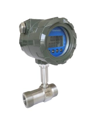
LWGYML series turbine flow meter is a new generation kind of flow meter that absorbs the advanced technologies of flow meter at home and abroad. It has been optimized and designed to have so many characteristics, such as simple structure, light weight, high precision, good repeatability,easy installation and usage.
2. Features
3. Application
Turbine flowmeters are widely used in the following measurement objects: petroleum, organic liquids, inorganic liquids, liquefied gas, natural gas, coal gas and cryogenic fluids. It is widely used in the transfer and gathering stations of foreign liquefied petroleum gas, refined oil and light crude oil, and the first and last stations of large crude oil pipelines for trade settlement. In Europe and the United States, turbine flow meters are second only to orifice flow meters for natural gas measurement. In the Netherlands alone, more than 2,600 gas turbine flow meters of various sizes and pressures ranging from 0.8 MPa to 6.5 MPa are used in natural gas pipelines. Has become an excellent natural gas flow meter. Although the excellent metering characteristics of turbine flowmeters are favored by people, they give people the impression that they are made of movable parts and have a short service life. They can't help but hesitate when choosing them. After people's unremitting efforts, it should be said that the situation has improved greatly. Turbine flowmeter, as the most common flowmeter, has developed into a multi-variety, full-series, and multi-specification mass production scale. In addition to a large number of applications in the aforementioned industrial sectors, turbine flowmeters are also widely used in some special sectors, such as scientific research, national defense science and technology, and measurement sectors. The use of these fields just avoids its weaknesses (not suitable for long-term continuous use) and gives full play to Its characteristics (high precision, good repeatability, can be used in high pressure, high temperature, low temperature and micro flow conditions). In these fields, most of them are designed according to the special requirements of the tested objects. They are special instruments and are not mass-produced.
4. Specifications
Pipeline Diameter(mm) and Connection | 4,6,10,15,20,25,32,40 Thread Connection |
(15,20,25,32,40) 50,65,80,100,125,150,200 Flange Connection | |
Accuracy | ±1%R,±0.5%R,±0.2%R(Special Order) |
Turn Down Ratio | 10:1; 15:1; 20:1 |
Material | 304SS,316(L)SS, etc |
Medium Temperature | -20℃~+110℃ |
Environmental Conditions | Temperature: -10℃~+55℃ Relative humidity: 5%~90% Atmospheric pressure: 86~106KPa |
Power supply | Sensor:+12VDC,+24VDC(Option) Transmitter:+24VDC Local Display:3.2V Lithium Battery |
Output Signal | Sensor:Pulse Frequency Signal(Low level≤0.8V, High level≥8V) Transmitter:Two Wired 4-20mA Current Signal |
Signal Cable | STVPV 3x0.3(Three Wired),2x0.3(Two Wired) |
Signal Cable Connection | Houseman Connector(Standard Type) Inner Thread M20x1.5(Explosion Type) |
Transmission Distance | ≤1000m |
Explosion Proof | None(Standard Type) EXdIIBT6(Explosion Proof) |
Protection Class | IP65 |
5. Installation Dimension
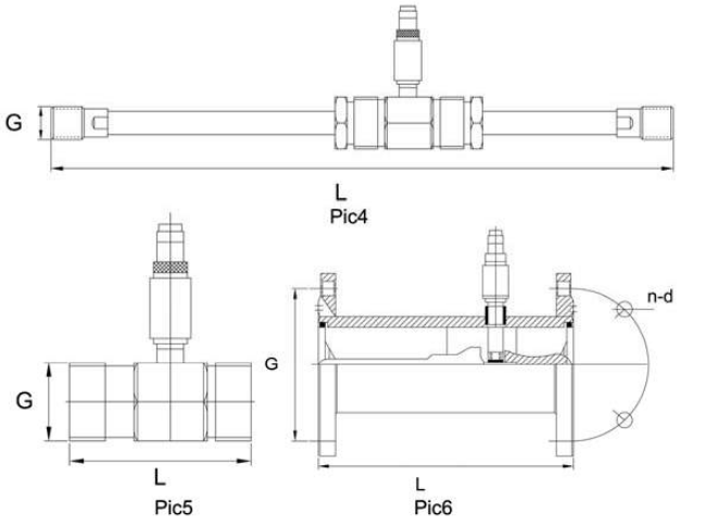
According to the diameter, choose thread or flange connection to install the senor. As to installation method, please check Pic4, Pic5, Pic6.
Pic4 LWGYML-4~10 Structure & Installation Dimension Diagram
Pic5 LWGYML-15~40 Structure & Installation Dimension Diagram
Pic6 LWGYML-50~200 Structure & Installation Dimension Diagram
Pipeline Diameter | L | Thread Connection | Flange Connection | ||
(mm) | G | D (mm) | d (mm) | n | |
DN4 | 295 | G1/2 | |||
DN6 | 330 | G1/2 | |||
DN10 | 450 | G1/2 | |||
DN15 | 75 | G1 | θ65 | θ14 | 4 |
DN20 | 80 | G1 | θ75 | θ14 | 4 |
DN25 | 100 | G1-1/4 | θ85 | θ14 | 4 |
DN32 | 120 | G2 | θ100 | θ14 | 4 |
DN40 | 140 | G2 | θ110 | θ18 | 4 |
DN50 | 150 | θ125 | θ18 | 4 | |
DN65 | 170 | θ145 | θ18 | 4 | |
DN80 | 200 | θ160 | θ18 | 8 | |
DN100 | 220 | θ180 | θ18 | 8 | |
DN125 | 250 | θ210 | θ25 | 8 | |
DN150 | 300 | θ250 | θ25 | 8 | |
DN200 | 360 | θ295 | θ25 | 12 |
6. Configuration
LWGYML Series Turbine Flow Meter Configuration | ||||||||||
Model | LWGYML | |||||||||
Pipe Material | 4 | 4mm | ||||||||
6 | 6mm | |||||||||
10 | 10mm | |||||||||
...... | ||||||||||
200 | 200mm | |||||||||
Model Description | N | No Display,12VDC Power Supply,Pulse Output, High Level≥8V Low Level≤0.8V | ||||||||
A | No Display,4-20mA 2 Wired Current Output | |||||||||
B | Local Display,Battery Operated | |||||||||
C | Local Display,4-20mA 2 Wired Current Output | |||||||||
C1 | Local Display,RS485 Output | |||||||||
C2 | Local Display, HART Output | |||||||||
Accuracy | 05 | 0.5 Grade | ||||||||
10 | 1.0 Grade | |||||||||
Turbine Type | W | Extended Ratio | ||||||||
S | Standard Ratio | |||||||||
Material | S | SS 304 | ||||||||
I | SS 316(L) | |||||||||
Explosion Proof | N | None | ||||||||
E | Explosion Type(ExmIICT6 or ExdIIBT6) | |||||||||
Pressure Rate | N | Normal Pressure | ||||||||
H | High Pressure | |||||||||
Connection Type | T | Thread Connection | ||||||||
F | Flange Connection | |||||||||
Filter | N | None | ||||||||
F | With Filter |
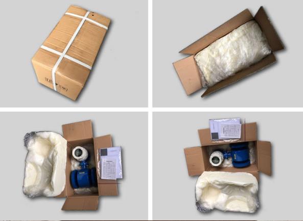
7. Product Packing