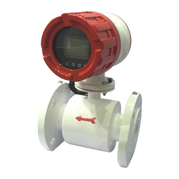
DN50 Digital Industrial Flow Meter / Electromagnetic Water Flow Meter
1. Introduction
MLF electromagnetic flow meter, composed of sensor and converter, works based on Faraday’s law of electromagnetic induction law. It is used to measure electrical conductivity of liquid or solid. Generally, the electrical conductivity should be over 5υS/cm(electrical conductivity of tap water, raw water is about 100~500υS/cm),It can also be used to measure various media like acid, alkali, saline solution, paper pulp or pulp and so on. But these media can’t contain a lot of magnetic materials and bubbles.
MLF electromagnetic flow meter is a kind of instrument which is used for measuring the flow conductivity liquid. The meter is widely used in flow measuring of Metallurgy, Chemical Industry, Paper Industry,Environmental Protection, Oil Industry, Textile Industry, Food Industry and City Administration, Water Works,etc.
2. Quick Details
1). It is high resistance, fast response design can make undistorted collection of weak signal and fast response to the flow changes. Its range rate can reach 100:1.
2). It has the function of low conductivity measurement.
3). It has the consistency of converter’s interchange, which can avoid input parameters repeatedly.
4). Wide range of power supply mode is available (DC: 18V-36V/AC: 85V-265V).
5). It is the first domestic company that adopts the function of saving settings before delivery,which can avoid the loss of the parameters.
6). It adopts the international leading excitation technology, which circuit is simple, stable,and reliable.
7). It has the function of infrared remote control and button operation so as to make the operation more convenient.
8). It provides the function of zero correction of sensor and automatic zero adjustment.
9). It has Chinese, English, Korean, Polish, Turkish, French and Portuguese languages for option to satisfy different customers’ requirements.
3. Specification
MLF Type | Divided Type | Integrated Type | Explosive Proof Integrated Type | Battery Powered Type | Heat Energy Type |
Accuracy | ±0.2% or ±0.5% | ||||
Pipeline Diameter | DN10-DN2000 | DN10-DN600 | DN25-DN2000 | ||
Flange | GB, ANSI, JIS, BS, Others | ||||
Pressure | DN10-DN600 1.0 1.6 2.5 4.0MPa | ||||
DN700-DN2000 0.6 1.0 1.6MPa | |||||
Liner Material | CR, PTFE, PU, Hard Rubber, PFA, FEP(F46) | ||||
Conductivity | ≥5µs/cm(Please contact us if it is less than 5µs/cm) | ||||
Electrode | 316L SS, Hb, Ta, Ti, Hc, Tungsten Carbide, Others | ||||
Protection Class | IP65, IP66, IP67, IP68 | ||||
Medium Temperature | -25~180℃ (Please refer to liner material) | -25~80℃(Please refer to liner material) | -25~180℃ (Please refer to liner material) | ||
Ambient Temperature for Accuracy Influence | <±0.1%/10℃ or <±0.25%/10℃ at the ambient temperature of -25~60℃ | ||||
Repetability | ≤±0.1% or ±0.25% | ||||
Analog Output Error | ≤±0.02mA | ||||
Velocity | 0.3~10m/s | ||||
Electrical connection | M20x1.5 Seal Cartridge, GB1/2, NPT1/2 | ||||
Output | 4-20mA, Pulse, RS485, Hart, Profibus |
4. Dimensional Sketches
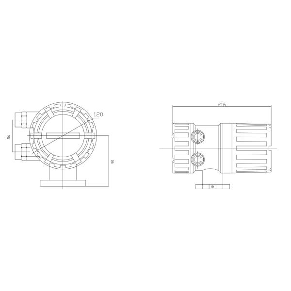
a. Dimension of Converter
Integrated Type
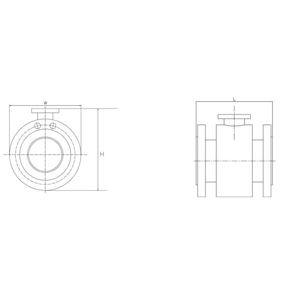
b. Dimension of Sensor
Pipeline Diameter | Dimension | ||
L | W | H | |
15 | 160 | 95 | 130 |
20 | 160 | 105 | 137 |
25 | 160 | 115 | 150 |
32 | 160 | 135 | 160 |
40 | 200 | 145 | 175 |
50 | 200 | 160 | 185 |
65 | 200 | 180 | 205 |
80 | 200 | 195 | 215 |
100 | 250 | 215 | 235 |
125 | 250 | 245 | 275 |
150 | 300 | 280 | 300 |
200 | 350 | 335 | 355 |
250 | 400 | 400 | 405 |
300 | 500 | 455 | 460 |
350 | 500 | 515 | 520 |
400 | 600 | 575 | 580 |
450 | 600 | 635 | 630 |
500 | 600 | 710 | 685 |
600 | 600 | 835 | 795 |
700 | 700 | 905 | 910 |
800 | 800 | 1020 | 1030 |
900 | 900 | 1120 | 1120 |
1000 | 1000 | 1245 | 1250 |
1200 | 1200 | 1465 | 1470 |
5. Configuration
MLF Series Electromagnetic Flow Meter Configuration | |||||||||||||||||||||||
Model | MLF | ||||||||||||||||||||||
Sensor Installation | S | Flange Type Sensor | |||||||||||||||||||||
C | Insertion Type Sensor | ||||||||||||||||||||||
O | Others | ||||||||||||||||||||||
Pipeline Diameter | 10 | 10mm | |||||||||||||||||||||
15 | 15mm | ||||||||||||||||||||||
20 | 20mm | ||||||||||||||||||||||
...... | |||||||||||||||||||||||
2000 | 2000mm | ||||||||||||||||||||||
Electrode Installation | F | Standard Fixed Type | |||||||||||||||||||||
Electrode Material | A | 316L SS | |||||||||||||||||||||
B | Hb | ||||||||||||||||||||||
C | Ta | ||||||||||||||||||||||
D | Ti | ||||||||||||||||||||||
E | Hc | ||||||||||||||||||||||
F | Tungsten Carbide | ||||||||||||||||||||||
G | Others | ||||||||||||||||||||||
Liner Material | R | Rubber | |||||||||||||||||||||
P | PTFE | ||||||||||||||||||||||
O | Others | ||||||||||||||||||||||
Pipe Material | B | 304 SS (Standard) | |||||||||||||||||||||
C | 316 SS | ||||||||||||||||||||||
Flange Type | G | GB (Standard) | |||||||||||||||||||||
A | ANSI | ||||||||||||||||||||||
J | JIS | ||||||||||||||||||||||
B | BS | ||||||||||||||||||||||
O | Others | ||||||||||||||||||||||
Flange Material | A | 304 SS | |||||||||||||||||||||
B | 316 SS | ||||||||||||||||||||||
C | #20 Carbon Steel (Standard) | ||||||||||||||||||||||
Cover Material | D | 304 SS | |||||||||||||||||||||
E | 316 SS | ||||||||||||||||||||||
F | Carbon Steel+ Epoxy Metallic Paint (Standard) | ||||||||||||||||||||||
Matching Flange | 0 | Without Matching Flange (Standard) | |||||||||||||||||||||
1 | With Matching Flange | ||||||||||||||||||||||
Ground Ring | 0 | Without Ground Ring (Standard) | |||||||||||||||||||||
1 | With Ground Ring | ||||||||||||||||||||||
Rated Pressure | 10 | 1.0MPa | |||||||||||||||||||||
16 | 1.6MPa | ||||||||||||||||||||||
25 | 2.5MPa | ||||||||||||||||||||||
40 | 4.0MPa | ||||||||||||||||||||||
Working Temperature | E | ≤60℃ | |||||||||||||||||||||
H | ≤180℃(Divided Type) | ||||||||||||||||||||||
Type | I | Integrated Type | |||||||||||||||||||||
D | Divided Type | ||||||||||||||||||||||
Output | P | Pulse | |||||||||||||||||||||
A | 4-20mA | ||||||||||||||||||||||
G | RS485 | ||||||||||||||||||||||
H | Hart | ||||||||||||||||||||||
Q | Others | ||||||||||||||||||||||
Power Supply | 0 | 220VAC | |||||||||||||||||||||
1 | 24VDC | ||||||||||||||||||||||
2 | Battery-powered | ||||||||||||||||||||||
Protection Class | 0 | IP65 (Integrated/Divided Type) | |||||||||||||||||||||
1 | IP67 (Divided Type) | ||||||||||||||||||||||
2 | IP68 (Divided Type) | ||||||||||||||||||||||
Other Features | R | Heat Energy Function | |||||||||||||||||||||
P | With PT1000 | ||||||||||||||||||||||
B | Without PT1000 | ||||||||||||||||||||||
Explosion Proof | 0 | None | |||||||||||||||||||||
EX | Explosive Proof |
6. Instrument Detection & Maintenance
Electromagnetic flow converter has self-diagnosis function. In addition to the power and hardware circuit fault, The system also give alarm to other faults in general usage. These information are given accordingly prompts in the lower right of the screen.
1. Maintenance and repair
a) Sensor installation site should be consistent with the section four requirements, Please keep the housing clean and tidy;
b)Transmitter should be placed in a clean, ventilated, dry place;
c)Need to inspect every two years, for high precision users, instrument need to be submitted to censorship.
2. Transportation and storage
a)The instrument must be packed before transportation, be carefully handled when loading and unloading.
b)Storage site must be dry, ventilated, avoid corrosive gas erosion, the ambient temperature is not too low or too high;
c)Storage time better not exceed three years.
3,Unpacking and checking
a) The packing can’t be opened with heavy hammer, and should becareful not to damage the instrument
b) Check the content carefully according to the packing list.