Gas Turbine Flow Meters / Turbine Flowmeter
1. Introduction
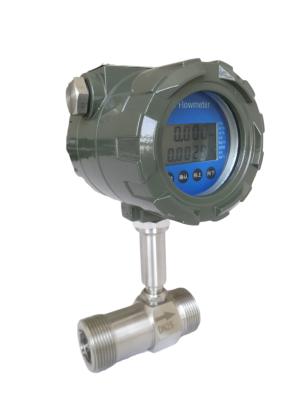
LWGYML series intelligent liquid turbine Flowmeter is a new type of intelligent instrument with the integration of turbine flow sensor and display accumulation developed by advanced ultra-low power consumption single-chip microcomputer technology. it has the advantages of compact mechanism, intuitive and clear reading, high reliability, no interference from external power supply, anti-lightning strike, low cost and so on.
2. Features
3. Specifications
Pipeline Diameter(mm) and Connection | 4,6,10,15,20,25,32,40 Thread Connection |
(15,20,25,32,40) 50,65,80,100,125,150,200 Flange Connection | |
Accuracy | ±1%R,±0.5%R,±0.2%R(Special Order) |
Turn Down Ratio | 10:1; 15:1; 20:1 |
Material | 304SS,316(L)SS, etc |
Medium Temperature | -20℃~+110℃ |
Environmental Conditions | Temperature: -10℃~+55℃ Relative humidity: 5%~90% Atmospheric pressure: 86~106KPa |
Power supply | Sensor:+12VDC,+24VDC(Option) Transmitter:+24VDC Local Display:3.2V Lithium Battery |
Output Signal | Sensor:Pulse Frequency Signal(Low level≤0.8V, High level≥8V) Transmitter:Two Wired 4-20mA Current Signal |
Signal Cable | STVPV 3x0.3(Three Wired),2x0.3(Two Wired) |
Signal Cable Connection | Houseman Connector(Standard Type) Inner Thread M20x1.5(Explosion Type) |
Transmission Distance | ≤1000m |
Explosion Proof | None(Standard Type) EXdIIBT6(Explosion Proof) |
Protection Class | IP65 |
4. Installation Dimension
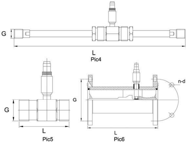
According to the diameter, choose thread or flange connection to install the senor. As to installation method, please check Pic4, Pic5, Pic6.
Pic4 LWGYML-4~10 Structure & Installation Dimension Diagram
Pic5 LWGYML-15~40 Structure & Installation Dimension Diagram
Pic6 LWGYML-50~200 Structure & Installation Dimension Diagram
Pipeline Diameter | L | Thread Connection | Flange Connection | ||
(mm) | G | D (mm) | d (mm) | n | |
DN4 | 295 | G1/2 | |||
DN6 | 330 | G1/2 | |||
DN10 | 450 | G1/2 | |||
DN15 | 75 | G1 | θ65 | θ14 | 4 |
DN20 | 80 | G1 | θ75 | θ14 | 4 |
DN25 | 100 | G1-1/4 | θ85 | θ14 | 4 |
DN32 | 120 | G2 | θ100 | θ14 | 4 |
DN40 | 140 | G2 | θ110 | θ18 | 4 |
DN50 | 150 | θ125 | θ18 | 4 | |
DN65 | 170 | θ145 | θ18 | 4 | |
DN80 | 200 | θ160 | θ18 | 8 | |
DN100 | 220 | θ180 | θ18 | 8 | |
DN125 | 250 | θ210 | θ25 | 8 | |
DN150 | 300 | θ250 | θ25 | 8 | |
DN200 | 360 | θ295 | θ25 | 12 |
5. Configuration
LWGYML Series Turbine Flow Meter Configuration | ||||||||||
Model | LWGYML | |||||||||
Pipe Material | 4 | 4mm | ||||||||
6 | 6mm | |||||||||
10 | 10mm | |||||||||
...... | ||||||||||
200 | 200mm | |||||||||
Model Description | N | No Display,12VDC Power Supply,Pulse Output, High Level≥8V Low Level≤0.8V | ||||||||
A | No Display,4-20mA 2 Wired Current Output | |||||||||
B | Local Display,Battery Operated | |||||||||
C | Local Display,4-20mA 2 Wired Current Output | |||||||||
C1 | Local Display,RS485 Output | |||||||||
C2 | Local Display, HART Output | |||||||||
Accuracy | 05 | 0.5 Grade | ||||||||
10 | 1.0 Grade | |||||||||
Turbine Type | W | Extended Ratio | ||||||||
S | Standard Ratio | |||||||||
Material | S | SS 304 | ||||||||
I | SS 316(L) | |||||||||
Explosion Proof | N | None | ||||||||
E | Explosion Type(ExmIICT6 or ExdIIBT6) | |||||||||
Pressure Rate | N | Normal Pressure | ||||||||
H | High Pressure | |||||||||
Connection Type | T | Thread Connection | ||||||||
F | Flange Connection | |||||||||
Filter | N | None | ||||||||
F | With Filter |
6. Details