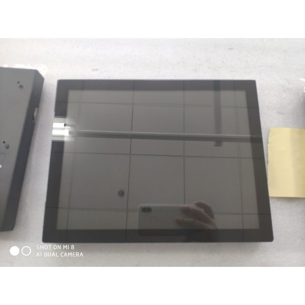
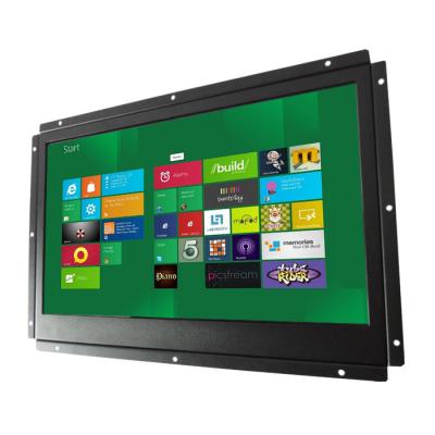
12 open frame monitor resistive touch screen IP65 front low cost
1. BASIC PARAMETERS
LCD Panel | Model Name | ITD12OFT1M1 |
Display Size | 12.1” | |
Panel Type | a-Si TFT active matrix | |
Pixel Format | 800 x 600 | |
Active Area | 245.76 (H) x 184.32(V) | |
Pixel Pitch | 0.240(H) x 0.240(H)mm | |
Colors | 262K/16.7M | |
Brightness | 300 (cd/㎡) (Typ.) | |
Contrast | 700:1 (Typ.) | |
Response Time | 16ms(TYP.) | |
Viewing Angles | 150(H)/130(V) | |
YPbPr(option) | 480i,480p,576i,576p 720p,1080i,1080p | |
PC-RGB | VGA:640x480/720x400 SVGA:800x600 XGA:1024x768 SXGA:1280x1024/1400x1050 UXGA:1680x1200/1680x1050 WXGA:1366x768 WUXGA:1920x1080/1920x1200 | |
DVI | DVI-I | |
HDMI(A type) | 480i,480p,576i,576p 720p,1080i,1080p | |
Audio Input Signals | PC Audio | Earphone Input 0.2~2.0VRMS |
Audio Output Signals | Frequency Response | 100Hz~15KHz @±3dB (1KHz, 0dB reference signal) |
Max Output Power | 2 x W(8Ω) THD+N<10%@1KHz (Power Supply: 12V, Audio Input: 0.5VRMS) | |
Touch Screen | Types | Resistive Touch, IR touch, PCAP touch, SAW Touch optional |
Connector | USB or RS232 | |
Operating System Support | Windows XP/7/8/10, Linux, Android, Mac, Raspberry Pi | |
Temperature | Operating Temperature | 0~+50℃(-20~+70℃ optional) |
Storage Temperature | -20~+70℃ | |
Humidity | Relatively Humidity | 10~90%RH |
Power Supply | Power Supply | 12V DC In |
Power Consumption | <25 W |
2. OSD MENU FUNCTION KEY
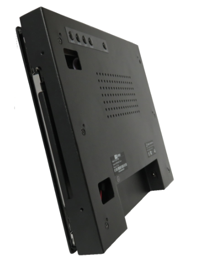
AUTO MENU LEFT RIGHT SELECT LED ON/OFF
NO | Button | Action |
1 | ON/OFF | Power on and off |
2 | Menu | 1. Enable/Disable OSD Menu. 2.Return to Previous Menu |
3 | Left/Decrease | 1. Decrease the Value. 2. Volume Hot Key. 3. Select the Menu |
4 | Right/Increase | 1. Increase the Value. 2. Volume Hot Key |
5 | EXIT | Select the Display Mode |
6 | AUTO | Move up Menu to Select |
7 | LED | Indicator |
3. OSD MENU ACTIONS
1). When no menu display, press the ‘MENU’ button. The Main Menu will be displayed. It contains 5 sub menus as ‘Color’,‘Adjust’,‘Sound’,‘Function’,‘OSD’. Press the ‘AUTO’ button to move up menu to select, and the ‘LEFT’ button to select the menu. The ‘LEFT’ or ‘RIGHT’ button is for changing the value. When need to exit the operation, press the ‘MENU’ button.
Here are the pictures:
2). When no menu display, press the ‘EXIT’ button. The Display Mode Menu will be displayed. Press the ‘AUTO’ button to move up menu to select, and the ‘LEFT’ button to select the menu. Then the display mode will be changed.
3). When no menu display, press the volume hot button (‘LEFT’ or ‘RIGHT’). The Volume Menu will be displayed. Press the ‘LEFT’ or ‘RIGHT’ button to change the volume. When need to exit the operation, press the ‘MENU’ button.
4. INPUT/OUTPUT CONNECTOR DEFINITION
NO. | Description |
1 | DC IN |
2 | HDMI IN |
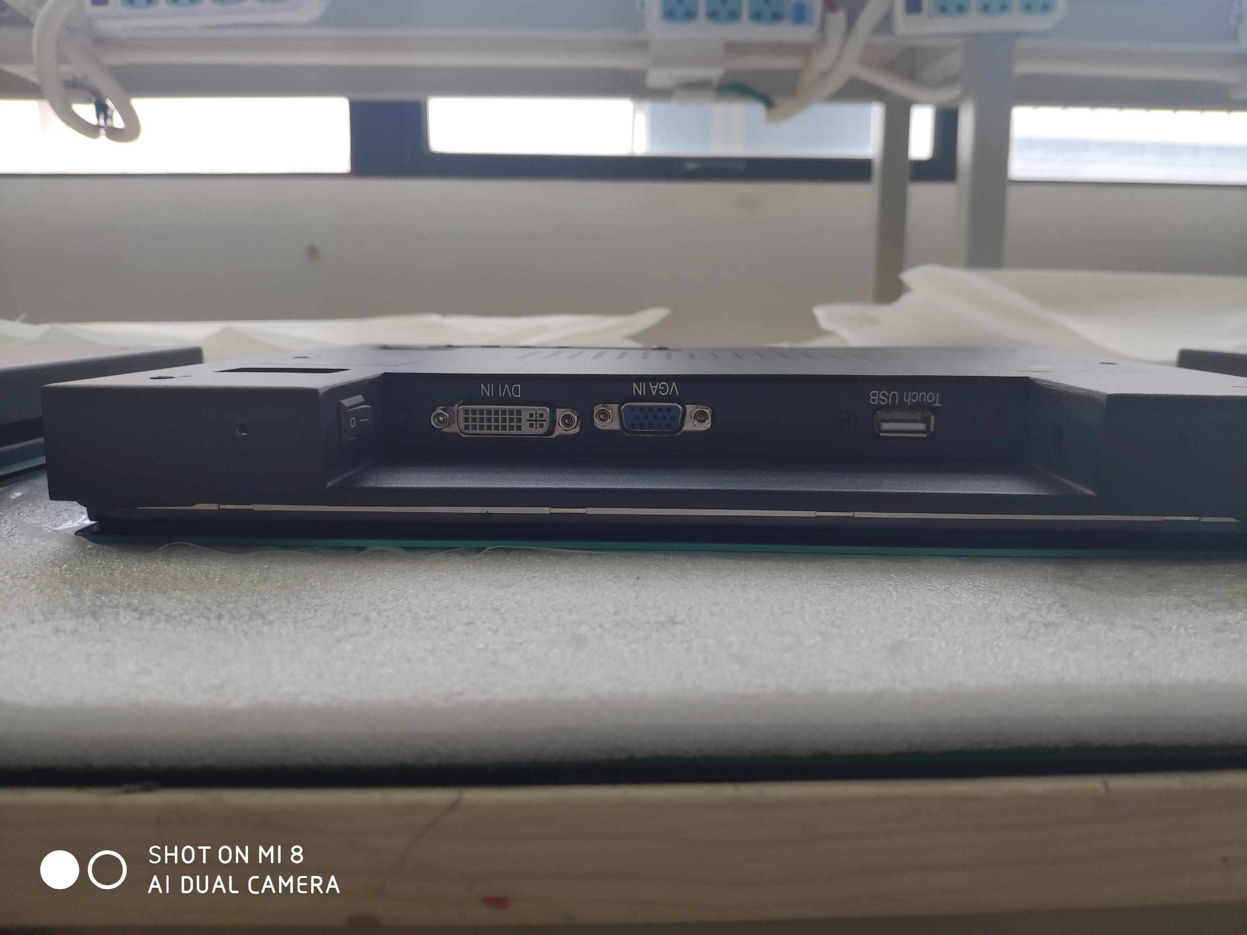
3 | DVI IN |
4 | VGA IN |
5 | PC AUDIO IN |
6 | EARPHONE OUT |
1). Top/Front Views
2). VGA (D-SUB DB15) Signal Definitions:
3). DVI Signal Definitions:
4). HDMI Signal Definitions:
PIN | DESCRIPTION |
1 | TMDS Data2+ |
2 | TMDS Data2 Shield |
3 | TMDS Data2– |
4 | TMDS Data1+ |
5 | TMDS Data1 Shield |
6 | TMDS Data1– |
7 | TMDS Data0+ |
8 | TMDS Data0 Shield |
9 | TMDS Data0– |
10 | TMDS Clock+ |
11 | TMDS Clock Shield |
12 | TMDS Clock– |
13 | CEC |
14 | Reserved (N.C. on device) |
15 | SCL |
16 | SDA |
17 | DDC/CEC Ground |
18 | +5V Power |