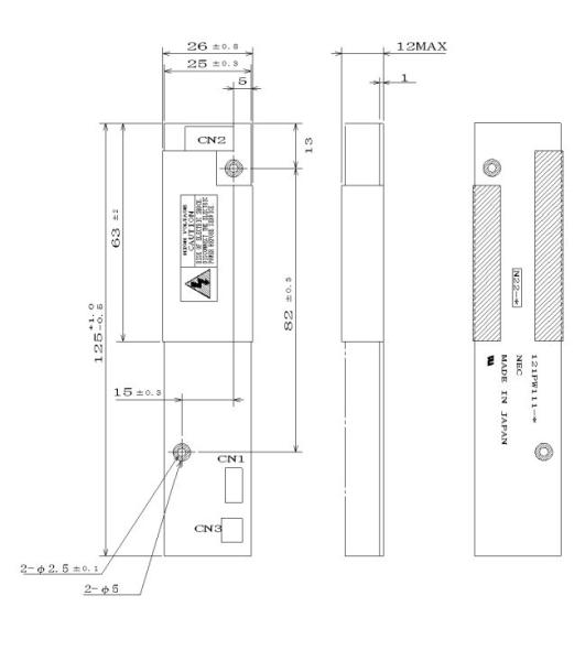
1.DESCRIPTION
21PW111 is type name of inverter. And the inverter consists of inverter circuit board, transformer and electric parts. Adaptable modules are as follows.
Adaptable LCD modules |
NL8060AC31-12, NL8060AC31-12G |
NL8060BC31-17, NL8060BC31-17D |
NL8060BC31-20 |
This inverter has luminance control functions.
· Two steps control by BRTHL terminal.
· Variable steps control by a voltage or variable resistor.
2.SPECIFICATION
2.1 GENERAL SPECIFICATIONS
Item | Specification | Unit | ||
+ 1.0 (V) | ||||
Inverter size | 26.0± 0.8 (H) ´ 125 | ´ 12.0 max. (D) | mm | |
- 0.5 (V) | ||||
Weight | 21(typ.), 25 (max.) | g | ||
Delivery unit | 10 (min.) | set |
2.2 ABSOLUTE MAXIMUM RATINGS
Parameter | Symbol | Rating | Unit | Remarks |
Storage temp. | Tst | -20 to +60 | °C | - |
Operating temp. | Top | 0 to +60 | °C | - |
Supply voltage | VDDB | 15 | V | Ta = 25°C |
Lamp voltage | VL | 1800 | Vrms | Ta = 25°C |
Relative Humidity Note1 | £ 95 | | Ta £ 40 °C | |
£ 85 | 40<Ta £ 50 °C | |||
Absolute Humidity Note1 | £ 70 Note2 | g/m3 | Ta > 50°C |
Note1: No condensation
Note2: Ta=50°C, RH=85%
2.3 ELECTRICAL CHARACTERISTICS
(1)Inverter
Parameter | Symbol | Min. | Typ. | Max. | Unit | Remarks |
Supply voltage | VDDB | 11.4 | 12.0 | 12.6 | V | - |
Supply current |
IDDB | - |
600 |
700 |
mA | Per two lamps VDDB=12.0V Luminance:100% |
Open lamp voltage | Vo | 1600 | 1700 | - | Vrms | Ta = 25°C |
Oscillator frequency | FO | 58 | 65 | 69 | kHz | Note 1 |
Luminance control range | - | - | 20-100 | - | % | Maximum luminance: 100% |
< Fuse >
Parameter | Fuse |
Rating | Fusing current Note1 | |
Type | Supplier | |||
VDDB |
11CT1A |
SOC Corporation | 1.0A |
2.0A |
72V |
Note1: The power supply capacity should be more than the fusing current.
If the power supply capacity is less than the fusing current, the fuse may not blow for a short time,
and then nasty smell, smoking and so on may occur.
3. Safety precautions
a.Because high voltage is present when the inverter is working, there is danger of electrical shock.
So that makes secure powered off when you handle the inverter.
b. Do not apply impulse and pressure to the inverter, otherwise the parts may damage.
c. There is danger that the inverter is charged at high voltage after use of the module, be sure to wait some time after switching power OFF before starting work.
d.Do not give the stress to interface connectors.
The module may become function deficiency by a contact defective and damages.
Pay attention to handling at the time of matching connector connection and in the connection condition.