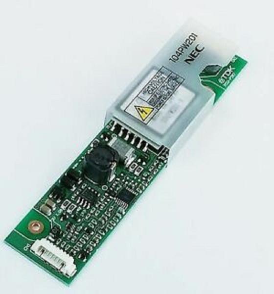
1. OUTLINE
This 104PW201 inverter is for LCD module. Adaptable LCD modules are as follows.
Adaptable LCD modules |
NL6448BC33-63C |
NL6448BC33-63D |
NL6448BC33-64 |
NL6448BC33-64C |
NL8048BC24-01 |
NL8060BC26-28 |
2. ABSOLUTE MAXIMUM RATINGS
Parameter | Symbol | Rating | Unit | Remarks | |
Power supply voltage | VDDB | 0 to +14.0 | V |
- | |
Input voltage | BRTC signal | VBC | -1.0 to VDDB+1.0 | V | |
BRTI signal | VBI | -1.0 to +5.0 | V | ||
Storage temperature | Tst | -30 to +80 | °C | - | |
Operating temperature | Top | -20 to +70 | °C | - | |
Relative humidity Note1 |
RH | £ 95 | % | Ta £ 40°C | |
£ 85 | % | 40 < Ta £ 50°C | |||
£ 55 | % | 50 < Ta £ 60°C | |||
£ 36 | % | 60 < Ta £ 70°C | |||
Absolute humidity Note1 | AH | £ 70 Note2 | g/m3 | Ta > 70°C |
Note1: No condensation
Note2: Water amount at Ta=70°C and RH=36%
3. ELECTRICAL CHARACTERISTICS
(Ta=25°C)
Parameter | Symbol | min. | typ. | max. | Unit | Remarks | |||
Power supply voltage | VDDB | 10.8 | 12.0 | 13.2 | V | Note1, Note2 | |||
Power supply current |
IDDB |
- |
530 |
600 | mA | (at the maximum luminance control.) Note2 | |||
Input voltage |
BRTC signal | High | VBCH | 2.0 | - | VDDB | V |
- | |
Low | VBCL | 0 | - | 0.8 | V | ||||
BRTI signal | VBI | 0 | - | 2.5 | V | ||||
Input current |
BRTC signal | High | IBCH | - | - | 1670 | mA |
- | |
Low | IBCL | -170 | - | - | mA | ||||
BRTI signal | IBI | -670 | - | -350 | mA | ||||
Output voltage | Open lamp voltage | VO | 1750 | - | - | Vrms | Ta = -20 to +70 | ||
Lamp voltage (at steady state) | VBLH | - | 520 | - | Vrms | - | |||
AM signal | High | VAMH | 4.5 | 5.0 | 5.5 | V | at malfunction | ||
Low | VAML | - | - | 0.5 | V | at normal | |||
Output current | Lamp current (per lamp) | IBL | 4.5 | 5.0 | 5.5 | mArms | at the maximum luminance control | ||
Oscillation frequency | FO | 63.5 | 67.5 | 72.0 | kHz |
- | |||
Luminance control frequency | FB | 241 | 255 | 268 | Hz |
Note1: When designing of the power supply, take the measures for the prevention of surge voltage.
Note2: The power supply lines (VDDB and GNDB) have large ripple voltage during luminance control of LCD lamps.
There is the possibility that the ripple voltage produces acoustic noise and signal wave noise in audio circuit and so on.
Put a capacitor (5,000 to 6,000mF) between the power supply lines (VDDB and GNDB) to reduce the noise,
if the noise occurred in the circuit.
4. FUSE
Parameter | Rating | Fusing current | Remarks | ||
VDDB |
CCP2E20HTTE |
KOA Corporation | 1.0A |
2.0A |
Note1 |
72V |
Note1: The power supply capacity should be more than the fusing current.
If it is less than the fusing current, the fuse may not blow in a short time,
and then nasty smell, smoke and so on may occur.