Yaskawa Output 4.4AMPS SERVO PACK Industrial Servo Drives 750Watt SGDE-08AP
Quick Details
SGDA08AP
SGDA08AP
SERVO DRIVE
7500W
11.0AMP
50/60HZ
AMPLIFIER
SIGMA
200V
POSITION
AVAILABLE
REBUILT SURPLUS
NEVER USED SURPLUS
REPAIR YOURS
24-48 HOUR RUSH REPAIR
2 - 15 DAY REPAIR
2 YEAR RADWELL WARRANTY
Similar Products
SGDE02BP SERVO DRIVE
SGDE02VP 4.0AMP 1PHASE 50/60HZ 200/230VAC
SGDE03BS SERVO DRIVE
SGDE04AP 200-230VAC 50/60HZ 6A
SGDE04AS SERVO DRIVE
SGDE08AP SERVO DRIVE
SGDE08APY1 SERVO DRIVE
SGDE08AS SERVO DRIVE
SGDE08VP(R) SERVO DRIVE
SGDE08VPR SERVO DRIVE
SGDE08VS 11AMP 1PHASE 50/60HZ 200/230VAC
SGDEA3AP SERVO DRIVE
SGDEA3VP SERVO DRIVE
SGDEA5AP SERVO DRIVE
SGDEA5BP SERVO DRIVE
SGDEA5BS SERVO DRIVE
SGDEA5VP SERVO DRIVE
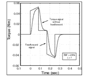
Feedforward control goes a long way towards reducing settling times and minimizing overshoot; however, there are several of assumptions that ultimately limit its effectiveness. For example, servo amplifiers all have current limits and finite respons e times. For motion bandwidths in the sub 50 Hz range, the current loops can be safely ignored; however, as the need to push the motion bandwidths higher, the current loops ne ed to be accounted for as well. In addition, the single most limiting factor in servo motion control is the resolution and accuracy of the feedback device. Lowresolution encoders contribute to poor velocity estimations that lead to either limit cycling or velocity ripple problems. Finally, compliant couplers that connect the load to the servomotor must also be accounted for as they too limit the useable motion bandwidths.
In summary, disturbance rejection control can be obtained by one of a number of ways, the two most common are P.I.D. and P.I.V. control. The direct use of P.I.D. control can often meet lowperformance
motion control loops and are generally set by either the Ziegler Nichols or by trialand-error methods. Overshoot and rise times are tightly coupled, making gain adjustments difficult. P.I.V. control, on the other hand, provides a method to significantly decouple the overshoot and rise time, allowing for easy set up and very high disturbance rejection characteristics. Finally, feedforward control is needed in addition to disturbance rejection control to minimize the tracking error.

One obvious way to increase the Xux density is to increase the current in the coil, or to add more turns. We Wnd that if we double the current, or a b
Figure 1.6 Multi-turn cylindrical coil and pattern of magnetic Xux produced by current in the coil. (For the sake of clarity, only the outline of the coil is shown on the right.)
Electric Motors 9 the number of turns, we double the total Xux, thereby doubling the Xux density everywhere.
We quantify the ability of the coil to produce Xux in terms of its magnetomotive force (MMF). The MMF of the coil is simply the product of the number of turns (N) and the current (I), and is thus expressed in ampere-turns. A given MMF can be obtained with a large number of turns of thin wire carrying a low current, or a few turns of thick wire carrying a high current: as long as the product NI is constant,
the MMF is the same.
Electric circuit analogy
We have seen that the magnetic Xux which is set up is proportional to the MMF driving it. This points to a parallel with the electric circuit, where the current (amps) that Xows is proportional to the
EMF (volts) driving it.
In the electric circuit, current and EMF are related by Ohm’s Law, which is Current ¼ EMF
Resistance i:e: I ¼ V R (1:3)
OTHER SUPERIOR PRODUCTS
Yasakawa Motor, Driver SG- | Mitsubishi Motor HC-,HA- |
Westinghouse Modules 1C-,5X- | Emerson VE-,KJ- |
Honeywell TC-,TK- | GE Modules IC - |
Fanuc motor A0- | Yokogawa transmitter EJA- |