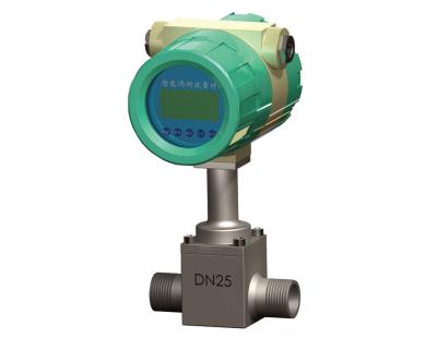
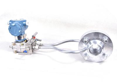
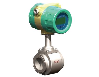
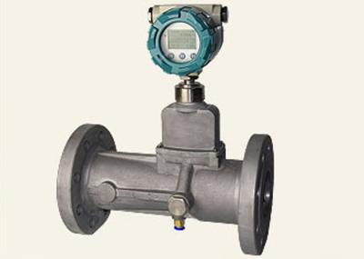
Turbine air steam flow meter for high pressure air flow measurement, PN40 Mpa, sanitary quick connect DN65
General introduction
The turbine flow meters, which use the mechanical energy of the fluid to rotate a “pinwheel” (rotor) in the flow stream. Blades on the rotor are angled to transform energy from the flow stream into rotational energy. Its rotor shaft spins on bearings. When the fluid moves faster, the rotor spins proportionally faster. Turbine flowmeters now constitute 7% of the world market.
The shaft rotations will be sensed mechanically or by detecting the movement of the blades. Blade movement is often detected magnetically, with each blade or embedded piece of metal generating a pulse. Turbine flowmeter sensors are typically located external to the flowing stream to avoid material of construction constraints that would result if wetted sensors were used. When the fluid moves faster, more pulses are generated. The transmitter processes the pulse signal to determine the flow of the fluid. Transmitters and sensing systems are available to sense flow in both the forward and reverse flow directions.
Features
Turbine blade option
Technical data
Diameter | Flow range | Temp. | Ambient Temp. | RH | Pressure | Pressure loss | ||
mm | +/- 1% | +/- 1.5% | +/- 2.5% | ℃ | ℃ | - | Mpa | KPa |
LWGQ15 | - | - | 1.5 ~ 7.5 | -20 ~ 60 | -20 ~ 50 | ≤95% | 6.4 | 1 |
LWGQ25 | - | - | 6 ~ 42 | 1 1.6 2.5 | ||||
LWGQ40 | 8.4 ~84 | 8.4 ~160 | 6.5 ~200 | |||||
LWGQ50 | 16.8 ~168 | 16.8 ~336 | 11 ~336 | |||||
LWGQ80 | 34 ~340 | 34 ~680 | 34 ~1000 | |||||
LWGQ100 | 51 ~510 | 51 ~1020 | 51 ~1850 | |||||
LWGQ150 | 98 ~980 | 98 ~1960 | 130 ~3000 | |||||
LWGQ200 | 170 ~1700 | 170 ~2550 | 140 ~4000 | |||||
LWGQ250 | 200 ~2000 | 200 ~3450 | 200 ~6000 | |||||
LWGQ300 | 400 ~4000 | 400 ~6000 | 250 ~7500 |
Model selection
Calculation logic of gas work flow and standard cubic flow converting
Formula: pV=nRT
P-pressure, V-measurement, n-material weight, R-constant, T-absolute temperature
Under ideal gas status, unit: pa (pressure), m3, mol,k, R=8.31
It’s actually to convert work flow into standard cubic flow at 20 C, 101.325kpa.
For example, work temp. T=32C, work pressure:P= 0.6 Mpa, work flow Qw=100 m3/h, the standard flow Qs:
Qs=100 * (701325*273) / (101325*305)=619.5345 m3/h
Applications:
For air, natural gas, coal gas flow metering volumetric measurement in petroleum, chemical processing, metallurgy. Combined with our accumulator, it can measure the gas / air cubic flow or weight flow.
Competitive advantage:
Lab equipment - Piston pressure regulator
Lab equipment - static flow calibrating line