high pressure air flow meter, Integrated orifice flowmeter for satuated steam,Pipe size DN15-DN800 mm
General introduction
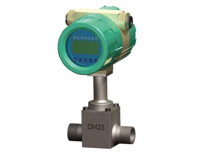
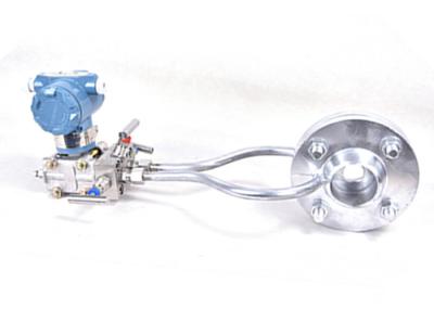
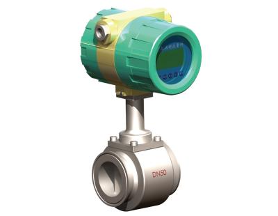
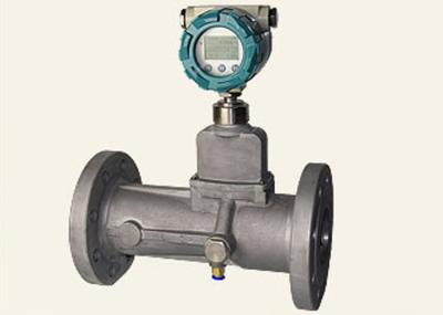
The configuration of ordinary differential pressure transmitters and ordinary flow display device integrated throttling flowmeter in the flow or pipe conditions change, without the replacement of throttling case, the use of "LG-94-01 version of the throttle Device design computer management software "to recalculate outflow coefficient C, coefficient of expansion ε, full-scale differential pressure value (or full-scale flow value), to modify the flow display device settings and adjust the differential pressure transmitter range. An intelligent, differential pressure transmitter with an integrated throttling flowmeter enables wide-range detection. Flow measurement up to 10: 1 or wider.
Integrated throttle flowmeter and differential pressure transmitter into one. Differential pressure transmitter and flow display device through the analog signal (4 ~ 20mA) or digital signal (HART protocol) communication, constitute the flow measurement system. The system uses digital integrated throttle flowmeter communication (HART protocol) flow measurement range up to 10: 1 or wider. The integrated throttling flowmeter inherits the medium to adapt to the throttling medium (liquid, gas, steam, general), no moving parts, without the actual calibration (can be measured using the geometric dry method), high temperature and pressure, impact resistance is not easy Deformation and other advantages. At the same time, the system design of antifreeze isolator, instrumentation department need insulation, with heat and condenser, the structure is more reasonable, easy to install, greatly reducing the amount of maintenance. Due to the use of antifreeze isolator greatly reduces the length of the lead tube, low failure rate, good dynamic characteristics.
Product features
Mounting notice:
The installation of the throttling device is suitable for the following pipe sections and pipe fittings: the first resistance element on the upstream side of the throttling member, the second resistance element, the first resistance element on the right under the throttling element, the second resistance element on the upstream from the throttling element Downstream of the first resistance between the pipe section and the differential pressure signal pipeline. The main need is based on the measurement medium to choose a suitable way of measuring the pressure tube and a sufficient length of straight pipe before and after.
Technical data
Diameter | DN15 - DN2000 |
Wet part material | Mo2Ti,Hc,Hb,Ta,Pt,SUS304,SUS316 |
Accuracy | ±1.0%,±1.5% |
Housing material | carbon steel, stainless steel, 12cr1MoV, etc |
Flow velocity range | 0.2 - 11 m/s |
Tempearture | 25℃~800℃ |
Pressure rating | 0.25Mpa-60Mpa |
Cable interface | PG10 |
Protection (transducer) | IP65, IP67, IP68 |
Explosion proof | Exmdib IIBT4 |
Converter type | compact / remote |
Power supply | 85 - 265VAC, 18-36V DC |
Power consumption | <5w |
Structure
Dimensions
DN(mm) | L(mm) | D(mm) | H(mm) | Weight(kg) |
15 | 150 | 22 | 55 | 10 |
20 | 150 | 25 | 55 | 10 |
25 | 150 | 32 | 55 | 10 |
32 | 150 | 38 | 55 | 10 |
40 | 160 | 46 | 55 | 12 |
50 | 180 | 57 | 55 | 13 |
65 | 200 | 76 | 55 | 14 |
80 | 200 | 89 | 58 | 15 |
100 | 220 | 108 | 60 | 20 |
125 | 250 | 133 | 62 | 22 |
150 | 260 | 159 | 63 | 25 |
200 | 270 | 219 | 66 | 40 |
250 | 300 | 273 | 70 | 60 |
300 | 330 | 329 | 72 | 70 |
350 | 350 | 373 | 75 | 80 |
400 | 360 | 430 | 78 | 90 |
450 | 380 | 480 | 80 | 110 |
500 | 450 | 530 | 82 | 130 |
600 | 420 | 640 | 85 | 150 |
700 | 500 | 740 | 88 | 175 |
800 | 550 | 850 | 90 | 200 |