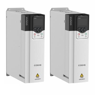
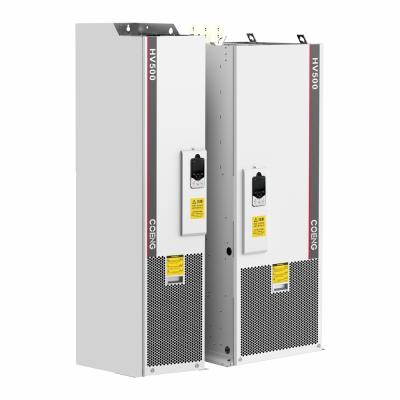
PERFORMANCE CHARACTERISTICS
Back-end quick debugging software
Powerful and easy to use, with functions such as parameter setting, real-time oscilloscope, fault recording, event recording, etc.
Excellent performance
Suspending at zero speed;
Torque response 1-3ms;
Extremely low dynamic speed drop and dynamic speed drop equivalent;
Excellent robustness;
Accurate off-line/online motor model identification.
Various needs satisfied
Standard LCD panel to improve user experience;
Master-slave control function;
Expandable communication card, encoding disk card, voltage detection card.
Ease of use
External 24V DC input power supported;
A Built-in brake unit is possible to save installation control;
Book style design to support seamless side-by-side installation.
Universality
Several international standard certifications passed, conforming to RoHS directives;
V/F, OLVC and CLVC control supported;
Several communication protocols supported;
Asynchronous and permanent magnet synchronous motors supported.
Durability
Mechanical vibration level 3M3;
Independent air duct design;
Conformal coating automatic spraying;
Built-in dynamic junction temperature model to facilitate product safety application.
MAIN PARAMETERS
Model | HV500 Low Voltage Engineering Single-Drive Inverter | |
iInput/output Power | Input Uin | 200V (-15%) ~240V (+10%) 3Phase , 380V (-15%) ~480V (+10%) 3Phase, |
500V (-15%) ~690V (+10%) 3Phase | ||
Input Frequency | 50Hz/60Hz±5% | |
Unbalance Degree of Uin | ≤3% | |
Output Uout | 0V~Input Uin | |
Output Frequency | 0Hz~500Hz | |
Power range | 2.2kW~560kW | |
Control Performance | Motor Type | Asynchronous / Synchronous |
Control Method | V/F, OLVC (Open-Loop Vector Control), CLVC (Close-Loop Vector Control) | |
Range of Speed Regulation | 1:10 V/F, 1:100 OLVC, 1:1000 CLVC | |
Start Torque | VF: 100% (0.5Hz), OLVC: 150% (0.5Hz), CLVC: 180% (0Hz) | |
Torque Precision | ≤5%, Vector Control | |
Torque Pulsation | ≤5%, Vector Control | |
Speed Regulation Precision | OLVC 0.2%, CLVC 0.01% | |
Torque Response | <5ms, Vector Control | |
Dynamic Speed Reduction | OLVC<0.5%*s, CLVC<0.3%*s | |
Acceleration and Deceleration Time | 0.0s~3200.0s, 0.0min~3200.0min | |
Torque Lifting | 0.0%~30.0% | |
Overload | Heavy Load Application 150% 1min/5min, Light Load Application 110% 1min/5min | |
V/F Curve | Multiple ways: linear V/F curve, 5 kinds of torque reduction characteristic curve mode (2.0 power, 1.8 power, 1.6 power, 1.4 power, 1.2 power), user-defined VF curve | |
Input Frequency Accuracy | Digital: 0.01Hz, Analog: 0.01Hz | |
Control Performance | Acceleration and Deceleration Curve | Straight, S Curve |
Multiple Speed-Steps Operation | 16-Speed Steps Operation through control terminals | |
Automatic VoltageAdjustment (AVR) | Keeping the output voltage constant automatically when the grid voltage changes within a certain range | |
Fixed Length | Setted and Fixed Length Control | |
In-build PID | It Can Easily Constructed Closed loop control system | |
Enhencement Function | Free Function Block | |
iInput/output | Set Frequency | Keyboaed, UP/DOWN Terminals, Multiple Speed-Steps Operation, Terminals Pulsation, Com |
Power | ||
Analog Input Terminals | AI1: 0V~10V/-10V~10V, AI2: 0V~10V/0(4) mA~20mA | |
Digital Input Terminals | DI1-DI6, 6 programmable digital input terminals, optocoupler isolation, compatible with drain/source input | |
Digital Input/Output Terminals | DIO1: Fast pulse output, normal input/output; DIO2: fast pulse input, normal input/output | |
Anolog Output Terminals | 2 Strings 0V~10V/0 (4) mA~20mA | |
Relay Output | 2Strings Contact Type FormC | |
Motor Temperature Detection | Support PT100/PT1000/KTY84 | |
STO Interface | SIL3/PLe Safe torque shutdown function | |
Com | Com Protocol | Modbus RTU (Standard), Profibus,CANopen,profinet,Devicenet,ControlNet |
profinet,Devicenet,ControlNet | ||
t | ||
Environment | Altitude | Without Derating Operation Within 2000m Altitude; 2000m~4000m, Each 100m lifting, Derating 1% (Current) |
Operation Temperature | -25℃~+40℃ (40℃~55℃ Derating) | |
Humidity | 15%~95%, Without Condensation | |
Vibration | 3M3, IEC60721-3-3 | |
Storage Temperature | -40℃~+70℃ | |
Operation Place | Indoor, Without direct sunlight, no flammable, corrosive gases, liquids and conductive particles | |
Accessory | Encoding card, communication expansion card, voltage detection card | |
Protection Function | Short circuit, over current, overload, over voltage, under voltage, phase loss, over temperature, external fault, etc. | |
Efficiency | 5.5kW~22kW: ≥93%; Above 30kW: ≥95% | |
Installation Method | Cabinet | |
Protection Degree | IP20 | |
Cooling | Forced Air Cooling |
Key Features
The inverter supports multiple control methods, including V/F, OLVC, and CLVC, allowing users to select the most appropriate mode for their specific application. This flexibility ensures that the inverter meets the operational requirements across different scenarios.
Equipped with user-friendly software, the HV500 Series offers powerful features for parameter setting, real-time monitoring, fault recording, and event logging. This simplifies the setup process and enhances the user experience.
With fast torque response times (1-3 ms) and excellent dynamic performance, the inverter minimizes speed drop and maintains stability during operation. Its ability to accurately identify motor models ensures optimal performance under varying conditions.
Designed with an independent air duct system and conformal coating, the inverter is built to resist mechanical vibrations and environmental challenges. It meets international standards for durability and has passed several certifications, ensuring compliance with industry regulations.
The standard LCD panel enhances the user interface, making it easier to operate and monitor the inverter. Additionally, the book-style design allows for seamless side-by-side installation, saving valuable space in control cabinets.
The HV500 Series is capable of operating across a broad input voltage range (from 200V to 690V), making it suitable for various installation environments and power requirements.