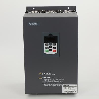
Self-developed Variable Speed Drive Inverter 380V 3 Phase 220kw For Food Processing Industry
VFD in practice
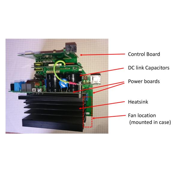
The power electronics usually come in a single package with a mounting plate – a power module. As these components dissipate heat, they need to be fixed to a heatsink, usually an aluminium extrusion or casting. The heatsink will have a fan or fans to cool it, except for the smallest units. It’s an advantage if the fan only switches on if the heatsink is getting hot, as the fans can wear out over time, as well as blow dirt, dust and fluids into the VFD.
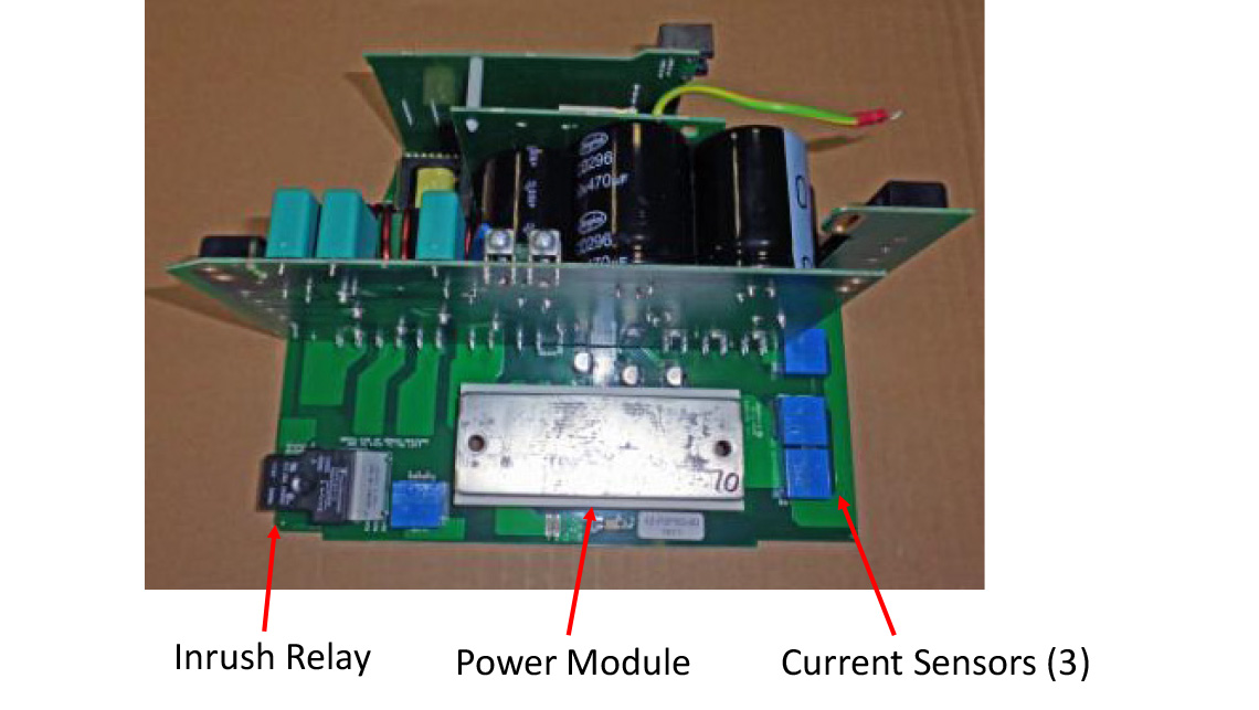
There will usually be at least one ’power’ printed circuit board close to the power module to carry the circuits associated with the IGBTs. There will be gate drive circuits, a power supply, current measurement circuits and an inrush circuit. All these will interface to the control circuit – more of this later.
Each IGBT requires a gate drive circuit. These turn the IGBT on and off as needed, and are connected directly to the IGBT and therefore to the power part of the variable frequency drive. The gate drives will also need a power supply, so actually four separate supplies are needed, one for each ‘upper’ IGBT and a common one for the three ‘lower’ IGBTs. As the power supply needs to supply the control electronics, the fans, and everything else, it becomes rather complicated. Usually a small IGBT supplies a high frequency transformer from the DC link, the secondaries of which feed the various supply regulators.
Current measurement is important and difficult in a variable frequency drive. Important because we need to monitor the output currents (to give good motor control and protection) and possible short circuit currents to protect the IGBTs. Difficult because the measurement points are in the output (or DC link) of the VFD and need power and isolation to get the signal back to the control circuitry. In practice this means using several Hall effect sensors to measure the current in the output, and one or two fast sensors or resistive shunts in the DC link.
The DC link capacitor will be mounted on a power board as well, and when the variable frequency drive is first switched on it will be uncharged, so a circuit consisting of a relay and resistor is used to limit the inrush current. The capacitor charges through the resistor and the relay shorts the resistor after a couple of seconds for normal operation.
So that’s the power pcbs. On the largest variable frequency drives they will be connected to the IGBTs and capacitors by hard wiring or bus bars; on smaller VFDs everything will be mounted onto one or more power boards.
The control electronics will usually be split between the power pcbs and the control board. A special integrated circuit on a power board will generate the on and off signals for the gate circuits. This will be controlled from the main processor on a separate control board; communication between the two will use a fast serial link. This makes isolation of the control board easier. It is important to remember that isolation here (using optocouplers) is necessary as the power pcb is connected to the DC link, and hence the mains.
FPR500A Product specifications
Basic Function | Specification | |
Maximum output frequency | 0~500Hz | |
Carrier frequency | 0.5kHz~16.0kHz;According to the load characteristics, carrier frequency can be adjusted automatically | |
Input frequency | Range :47~63Hz | |
Control mode | V/F Open/closed loop vector control(SVC/FVC) | |
Speed range | 1:50(Vector mode 0 ) 1Hz/150% rated torque | |
Overload capability | G type:150% rated current for 60s; 180% rated current for 3s 150% rated current for 3s | |
Torque boost | Auto Torque boost Manual Torque boost; 0.1%~30.0%. | |
V/F curve V/F | Four modes : Line , Multi-point , Square V/F curve, V/F separation | |
Jog control | Jog frequency range:0.00Hz to F0-10(Max frequency) | |
Accelerate/Decelerate curve | Line or S-curve Acc/Dec mode, four kinds of Acc/Dec time Range of Acc/Dec Time0.0~65000.00s. | |
DC brake | DC brake frequency: 0.00Hz to Maximum frequency brake time: 0.0 to 36.0s brake current value: 0.0 to 100% | |
Simple PLC, Multi-speed | 16-speed operating through built-in PLC or control terminal | |
Built-in PID | Close loop control system can be formed easily by using PID | |
Automatic voltage regulating (AVR) | Output voltage is regulated when voltage of the power network changes | |
Overvoltage and over current stall control | During operation automatically limits the inverter output current and bus voltage, to prevent fan over current and overvoltage trip. | |
Rapid current limiting function | Minimizing flow failures, protect the normal operation of the inverter | |
Instantaneous stop non-stop | Load feedback energy compensation voltage is reduced and continues to maintain a short time when change is momentarily interrupted. | |
Speed tracking start | For high-speed rotation of the motor speed identification, impact- free smooth start | |
Rapid current limit | Rapid software and hardware limiting technology to avoid frequent converter over current fault. | |
Virtual IO | Five sets of virtual DO, five sets of virtual DI, enables easy logic control. | |
Timing Control | Timing control: set the time range 0.0Min~6500.0Hour | |
Multi-motor switch | Two independent motor parameters, enabling two motors switching control | |
Bus Support | Two independent Modbus communication, CAN-Link | |
Command source | Given the control panel, control terminal, serial communication port given. It can be switched by a variety of ways. | |
Torque boost | Auto Torque boost Manual Torque boost ; 0.1%~30.0%. | |
Frequency source | Nine kinds of frequency sources: digital setting, analog voltage setting, analog current setting, pulse setting, or serial port and so on. It can be switched by a variety of ways. | |
Auxiliary frequency source | Nine kinds of auxiliary frequency source. Flexible implementation of auxiliary frequency tuning, frequency synthesis. | |
Input terminal | Six digital input terminals, one only supports 50khz high pulse input Two analog input terminals, one support 0V~10V voltage input One support 0 ~ 10V voltage input or 0 ~ 20mA current input | |
Output terminal | One high-speed pulse output terminal (optional open collector type), support of square wave 0 ~ 50kHz signal output One digital output terminal One relay output terminals Two analog output terminals, support 0 ~ 20mA current output or 0 ~ 10V voltage output | |
Display and operation | ||
LED display | Display parameters and status information | |
The key lock and function selection
| Achieve some or all of the keys locked, scope definition section keys to prevent misuse. |
Field Application Photos:
Company Profile:
Zhejiang Chifon electric Co., Ltd., is a high-tech enterprise specializing in research, development, manufacture and sales of electric drive, industrial control and motor energy saving technology products.
BEST SERVICE, WE DRIVE!