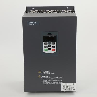
FPR500A Series Vector Variable Frequency Inverter For Fan Single Phase Motor 2.2kw
Power class
Single-phase 220v±15% 0.4-2.2kw
Three-phase 380V±15% 0.75-315kw
Product introduction
FPR500 series relies on TI company's DSP dual-core professional control motor chip, which supplies the international leading vector control algorithm to realize the real high-precision flux vector torque control. It has built-in pg vector control (VC), pg-free vector control (SVC), and V/F control modes, which are widely applied to high-speed control accuracy, rapid torque response, and high performance at low frequency. The integration of torque control, speed control, and position control can meet the high-performance requirements of customer applications. And, FPR 500 has the ability to exceed the anti-trip performance of similar products and adapt to the severe power grid, ambient temperature, humidity, and dust, greatly improving the reliability of products.
Products Specifications:
Basic Function | Specification | |
Maximum output frequency | 0~500Hz | |
Carrier frequency | 0.5kHz~16.0kHz;According to the load characteristics, carrier frequency can be adjusted automatically | |
Input frequency | Range :47~63Hz | |
Control mode | V/F Open/closed loop vector control(SVC/FVC) | |
Speed range | 1:50(Vector mode 0 ) 1Hz/150% rated torque | |
Overload capability | G type:150% rated current for 60s; 180% rated current for 3s P type:120% rated current for 60s; 150% rated current for 3s | |
Torque boost | Auto Torque boost Manual Torque boost; 0.1%~30.0%. | |
V/F curve V/F | Four modes : Line , Multi-point , Square V/F curve, V/F separation | |
Jog control | Jog frequency range:0.00Hz to F0-10(Max frequency) | |
Accelerate/Decelerate curve | Line or S-curve Acc/Dec mode, four kinds of Acc/Dec time Range of Acc/Dec Time0.0~65000.00s. | |
DC brake | DC brake frequency: 0.00Hz to Maximum frequency brake time: 0.0 to 36.0s brake current value: 0.0 to 100% | |
Simple PLC, Multi-speed | 16-speed operating through built-in PLC or control terminal | |
Built-in PID | Close loop control system can be formed easily by using PID | |
Automatic voltage regulating (AVR) | Output voltage is regulated when voltage of the power network changes | |
Overvoltage and over current stall control | During operation automatically limits the inverter output current and bus voltage, to prevent fan over current and overvoltage trip. | |
Rapid current limiting function | Minimizing flow failures, protect the normal operation of the inverter | |
Instantaneous stop non-stop | Load feedback energy compensation voltage is reduced and continues to maintain a short time when change is momentarily interrupted. | |
Speed tracking start | For high-speed rotation of the motor speed identification, impact- free smooth start | |
Rapid current limit | Rapid software and hardware limiting technology to avoid frequent converter over current fault. | |
Virtual IO | Five sets of virtual DO, five sets of virtual DI, enables easy logic control. | |
Timing Control | Timing control: set the time range 0.0Min~6500.0Hour | |
Multi-motor switch | Two independent motor parameters, enabling two motors switching control | |
Bus Support | Two independent Modbus communication, CAN-Link | |
Command source | Given the control panel, control terminal, serial communication port given. It can be switched by a variety of ways. | |
Torque boost | Auto Torque boost Manual Torque boost ; 0.1%~30.0%. | |
Frequency source | Nine kinds of frequency sources: digital setting, analog voltage setting, analog current setting, pulse setting, or serial port and so on. It can be switched by a variety of ways. | |
Auxiliary frequency source | Nine kinds of auxiliary frequency source. Flexible implementation of auxiliary frequency tuning, frequency synthesis. | |
Input terminal | Six digital input terminals, one only supports 50khz high pulse input Two analog input terminals, one support 0V~10V voltage input One support 0 ~ 10V voltage input or 0 ~ 20mA current input | |
Output terminal | One high-speed pulse output terminal (optional open collector type), support of square wave 0 ~ 50kHz signal output One digital output terminal One relay output terminals Two analog output terminals, support 0 ~ 20mA current output or 0 ~ 10V voltage output | |
Display and operation | ||
LED display | Display parameters and status information | |
The key lock and function selection | Achieve some or all of the keys locked, scope definition section keys to prevent misuse. | |
Protection function | Input/output phase failure protection ,Overcurrent protection ;Over voltage protection; Undervoltage protection; Overheat protection ; Overload protection | |
Options | Brake assembly, PG card | |
Environment | ||
Application environment | In-door, free from direct sunlight, dust , corrosive gas, combustible gas, oil mist , steam , water drop and salt . | |
Altitude | Lower than 1000m | |
Vibration | Less than 5.9m/s(0.6g) |
The process of sizing a VFD starts with the motor’s full load amps.
Match your motor’s FLA with the amp ratings of each VFD you consider. Or play it safe and get a VFD with a higher amp rating than your motor requires to give yourself a bit of cushion for constant torque loads and/or applications that require more strength during start up. If you don’t get a big enough drive, it will trip out every time you try to power up.
Load or motor horsepower is a great way to refine your search for drives fit for your application, but it shouldn’t be used as a direct reference for drive requirements. Due to variables in load requirements like RPM (a 900 RPM motor has a much different amp requirement than a 3600 RPM motor), sizing a VFD on HP alone will likely get you in trouble. We strongly recommend you use HP to narrow your selection but that you use amps (FLA) to determine the right VFD for your motor.
Voltage and Phase
You have to match the voltage of the VFD and motor to your available voltage on site. For low-voltage applications in the U.S., this is usually 208, 230 or 460 VAC. For medium voltage (1000 volts to 35kV) or other applications, it’s wise to call application specialists or engineers for assistance.
VFDs are primarily used in industrial facilities with three-phase power supply. A VFD can act as a phase converter if you have a three-phase motor but are limited to one-phase supply.
If your load is 3-horsepower or below (approx. <10 amps FLA), there are several single-phase input drives to consider. If your motor is greater than 3 HP, you could use a drive built for three-phase input so long as it has been de-rated correctly.
To properly de-rate your VFD to act as a phase converter for one-phase incoming power, start with your motors FLA. Multiply the motor FLA by two and select a VFD rated for twice the motor’s FLA. For example, if you have a 10 HP motor with a FLA of 28 amps, you’ll need a VFD rated more than 56 amps and around 20 HP.
For small shops or home use, keep in mind that VFDs are the number one power polluters on the planet. They pollute power quality even more when used as a phase converter. Talk to your sales engineer to see if using a line reactor is the right option for you.
Now let’s consider the work you’re doing. Do you need to run a pump, rotary kiln or an extruder? The answer will determine whether you need a variable or constant torque drive.
Variable torque drives are for simple centrifugal equipment like fans and pumps. These drives allow the motor to apply only the torque necessary to run the application at slower speeds. Centrifugal applications rarely exceed the rated current, so variable torque drives only need a one-minute overload current capacity of 120%.
Constant torque VFDs are necessary for heavier applications that require continuous torque at all speeds like conveyors, positive displacement pumps, punch presses and extruders. For example, a conveyor runs constantly, but it needs more power as weight is added to the belt, so your drive has to be able to handle the difference. That’s why constant torque drives need at least 150% one-minute overload current capacity to protect against load spikes.
You may think, let’s play it safe and go with constant torque even for a basic fan application. And if you absolutely can’t live without that fan, it could be a worthwhile precaution. But that’s like buying a sports car for your grandma — you’re spending a lot of money on performance that will never get used.
VFDs can under and over speed motors. A VFD can run your motor slow enough that its internal cooling fan isn’t moving enough air to keep the motor operational. Proper precautions should be implemented to protect your motor, such as use of a separate auxiliary cooling fan, if you plan to under speed your motor.
A VFD also can operate the motor faster than its nameplated RPM value. However, be advised that in doing so you will lose torque. We recommend you don’t go more than 20% above a motor‘s rated speed and that you check with your motor manufacturer before doing this to make sure over-speeding won’t void any warranties.
When buying a VFD, you’ll want to think through your method of control. Will you be controlling the VFD from a door mounted keypad or from a PLC?
Many manufacturers require Ethernet communications to get the right information from their drives to the PLC and production automation systems. More operations are moving to these advanced communication systems, but some inexpensive drives don’t include these options. So if you’re looking to advance your systems in the future, make sure you’re getting drives that won’t hold you back. Your sales engineer will be able to help you select the correct communication protocol based on your needs and preferences.
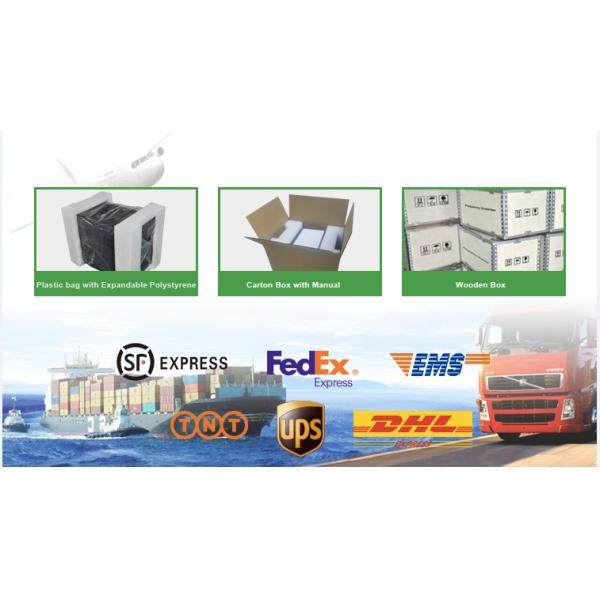
Packing details: