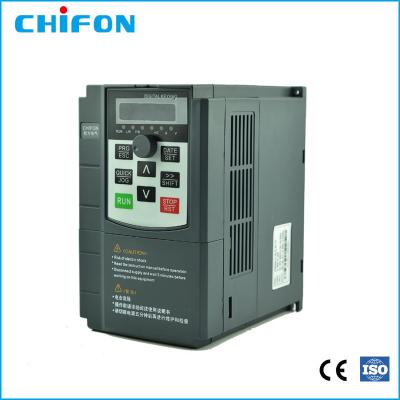
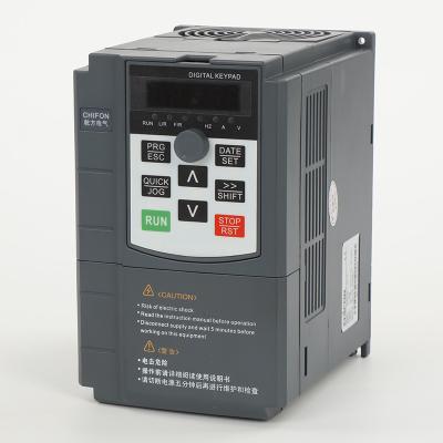
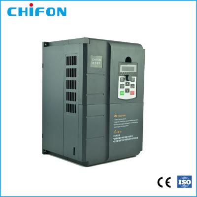
CE Certificated Variable Speed Drive VSD 380V 3 Phase 200kw For Water Pump Industry
Benefit of a Variable Speed Drive
No other AC motor control method compares to variable speed drives when it comes to accurate process control. Full-voltage (across the line) starters can only run the motor at full speed, and soft starts and reduced voltage soft starters can only gradually ramp the motor up to full speed, and back down to shutoff. Variable speed drives, on the other hand, can be programmed to run the motor at a precise speed, to stop at a precise position, or to apply a specific amount of torque.
In fact, modern AC variable speed drives are very close to DC drives in terms of fast torque response and speed accuracy. AC motors, however, are much more reliable and affordable than DC motors, making them far more prevalent.
Most drives used in the field utilize Volts/Hertz type control, which means they provide open-loop operation. These drives are unable to retrieve feedback from the process, but are sufficient for the majority of Variable Speed Drive applications. Many open-loop variable speed drives do offer slip compensation though, which enables the drive to measure its output current and estimate the difference in actual speed and the setpoint (the programmed input value). The drive will then automatically adjust itself towards the setpoint based on this estimation.
Most variable torque drives have PID capability for fan and pump applications, which allows the drive to hold the setpoint based on actual feedback from the process, rather than relying on an estimation. A transducer or transmitter is used to detect process variables such as pressure levels, liquid flow rate, air flow rate, or liquid level. Then the signal is sent to a PLC, which communicates the feedback from the process to the drive. The variable Speed Drive uses this continual feedback to adjust itself to hold the setpoint.
High levels of accuracy for other applications can also be achieved through drives that offer closed-loop operation. Closed-loop operation can be accomplished with either a field-oriented vector drive, or a sensorless vector drive. The field-oriented vector drive obtains process feedback from an encoder, which measures and transmits to the drive the speed and/or rate of the process, such as a conveyor, machine tool, or extruder. The drive then adjusts itself accordingly to sustain the programmed speed, rate, torque, and/or position.
Company Profile:
Zhejiang Chifon electric Co., Ltd., is a high-tech enterprise specializing in research, development, manufacture and sales of electric drive, industrial control and motor energy saving technology products.
BEST SERVICE, WE DRIVE!
FPR500A Product specifications
Basic Function | Specification | |
Maximum output frequency | 0~500Hz | |
Carrier frequency | 0.5kHz~16.0kHz;According to the load characteristics, carrier frequency can be adjusted automatically | |
Input frequency | Range :47~63Hz | |
Control mode | V/F Open/closed loop vector control(SVC/FVC) | |
Speed range | 1:50(Vector mode 0 ) 1Hz/150% rated torque | |
Overload capability | G type:150% rated current for 60s; 180% rated current for 3s 150% rated current for 3s | |
Torque boost | Auto Torque boost Manual Torque boost; 0.1%~30.0%. | |
V/F curve V/F | Four modes : Line , Multi-point , Square V/F curve, V/F separation | |
Jog control | Jog frequency range:0.00Hz to F0-10(Max frequency) | |
Accelerate/Decelerate curve | Line or S-curve Acc/Dec mode, four kinds of Acc/Dec time Range of Acc/Dec Time0.0~65000.00s. | |
DC brake | DC brake frequency: 0.00Hz to Maximum frequency brake time: 0.0 to 36.0s brake current value: 0.0 to 100% | |
Simple PLC, Multi-speed | 16-speed operating through built-in PLC or control terminal | |
Built-in PID | Close loop control system can be formed easily by using PID | |
Automatic voltage regulating (AVR) | Output voltage is regulated when voltage of the power network changes | |
Overvoltage and over current stall control | During operation automatically limits the inverter output current and bus voltage, to prevent fan over current and overvoltage trip. | |
Rapid current limiting function | Minimizing flow failures, protect the normal operation of the inverter | |
Instantaneous stop non-stop | Load feedback energy compensation voltage is reduced and continues to maintain a short time when change is momentarily interrupted. | |
Speed tracking start | For high-speed rotation of the motor speed identification, impact- free smooth start | |
Rapid current limit | Rapid software and hardware limiting technology to avoid frequent converter over current fault. | |
Virtual IO | Five sets of virtual DO, five sets of virtual DI, enables easy logic control. | |
Timing Control | Timing control: set the time range 0.0Min~6500.0Hour | |
Multi-motor switch | Two independent motor parameters, enabling two motors switching control | |
Bus Support | Two independent Modbus communication, CAN-Link | |
Command source | Given the control panel, control terminal, serial communication port given. It can be switched by a variety of ways. | |
Torque boost | Auto Torque boost Manual Torque boost ; 0.1%~30.0%. | |
Frequency source | Nine kinds of frequency sources: digital setting, analog voltage setting, analog current setting, pulse setting, or serial port and so on. It can be switched by a variety of ways. | |
Auxiliary frequency source | Nine kinds of auxiliary frequency source. Flexible implementation of auxiliary frequency tuning, frequency synthesis. | |
Input terminal | Six digital input terminals, one only supports 50khz high pulse input Two analog input terminals, one support 0V~10V voltage input One support 0 ~ 10V voltage input or 0 ~ 20mA current input | |
Output terminal | One high-speed pulse output terminal (optional open collector type), support of square wave 0 ~ 50kHz signal output One digital output terminal One relay output terminals Two analog output terminals, support 0 ~ 20mA current output or 0 ~ 10V voltage output | |
Display and operation | ||
LED display | Display parameters and status information | |
The key lock and function selection
| Achieve some or all of the keys locked, scope definition section keys to prevent misuse. | |
Protection function | Input/output phase failure protection ,Overcurrent protection ;Over voltage protection; Undervoltage protection; Overheat protection ; Overload protection | |
Options | Brake assembly, PG card | |
Environment | ||
Application environment | In-door, free from direct sunlight, dust , corrosive gas, combustible gas, oil mist , steam , water drop and salt . | |
Altitude | Lower than 1000m | |
Vibration | Less than 5.9m/s(0.6g) |
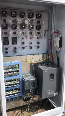
Field Application Photos:
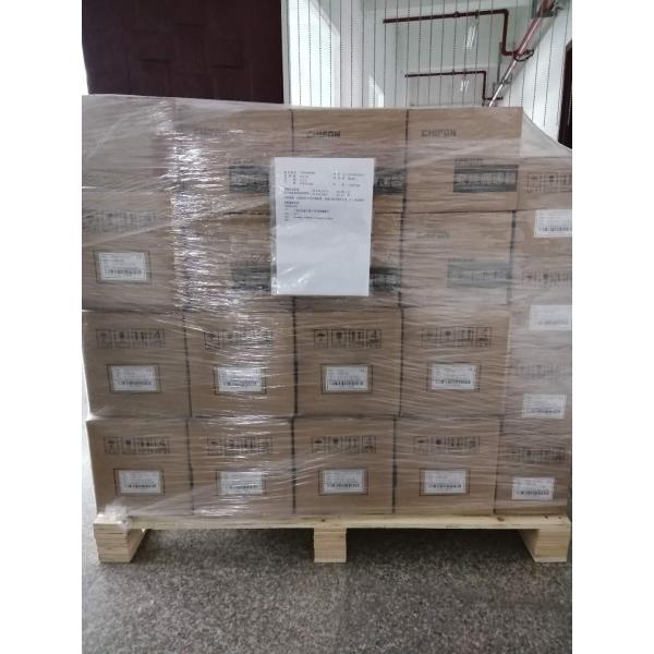
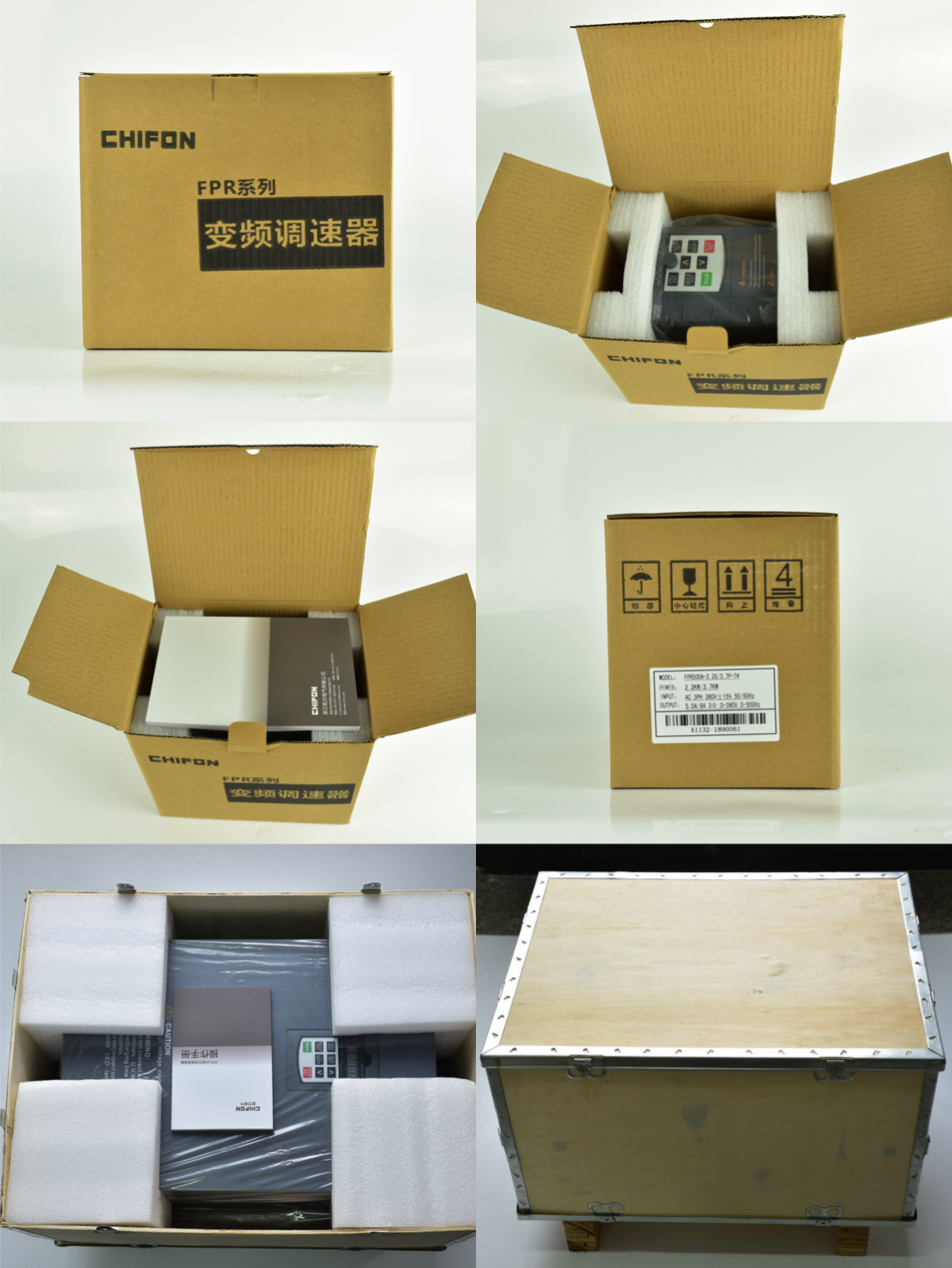
Product packaging: