Dniver Parameter | Min Value | Rated Value | Max Value |
Voltage input DC (V) | 14 | 48 | 56 |
Current output(A) | - | - | 15 |
Motor speed rang(rpm) | 0 | - | 20000 |
Hall signal voltag(V) | - | - | 5 |
Hall drive current (mA) | 12 | - | - |
External potentiometer (KQ) | - | 10 | - |
2.2 Environmental indicators
Environmental factor: | Environmental indicators |
Cooling method: | Natural cooling or forced cooling |
Usage occasion: | Avoid dust,oil stains,and corrosive gases |
Operating temperature: | +10℃ ~ +50℃ |
Environmental humidity: | 90%RH (non-condensing) |
Shock: | 5.9m/s²max |
Storage temperature: | 0℃~+50℃ |
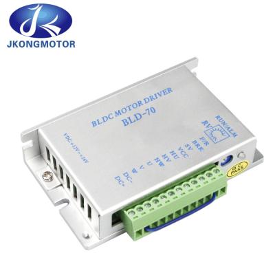
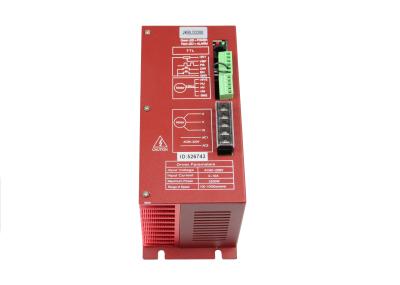
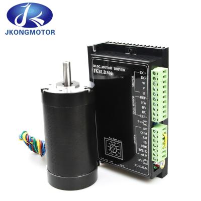
3. Driver interface and wiring diagram
3.1 Driver interface
3.2 Port signal description
4. Function Setting
4.1 Acceleration/deceleration time setting
Set the acceleration and deceleration time of the motor through the side potentiometer ACC/DEC of the
driver. Adjusting the potentiometer clockwise can increase the acceleration/deceleration time, while
adjusting the potentiometer counterclockwise can reduce the acceleration/deceleration time. Setting
range: 0.2-15S.
Note: Acceleration time refers to the time required for the motor to reach the rated speed from a
stationary state; The deceleration time refers to the time required for the motor to stop from the rated
speed.
4.2 Motor pole number setting
In order to better match DC brushless motors with different pole pairs, the pole pairs of the motor can be
set through the driver side dial switch SW1.
ON: 2 opposite poles;
OFF: 4 opposite poles.
Attention: When using closed-loop control, please first set SW1 based on the number of motor poles
4.3 Open/Closed Loop Control Settings
Select open loop control or closed loop control through the driver side dial switch SW2.
ON: closed-loop control;
OFF: Open loop control.
Attention: When using closed-loop control, please first set SW1 based on the number of motor poles.
4.4 Peak output current setting
Set the peak output current through the P-sv potentiometer in the middle of the driver interface. When
the load suddenly increases, the output current will be limited to the set value, reducing the motor speed
and protecting the motor from damage.
Please set the peak output current according to the scale on the driver's label, with a setting range of
3-15A.
Due to the error between the set value and the actual value being approximately ± 10%, to ensure safety,
please adjust the peak output current appropriately.
4.5 Locked rotor output current limit
When the motor is locked, the output current will be limited to 3A to protect the driver and motor from
damage.
4.6 Locked rotor torque maintenance function
When the motor is locked, the driver has a simple torque holding function.
Attention: Locked rotor holding torque is a short-term behavior, please do not use it for braking locked
rotor.
4.7 Restart function
When situations such as motor blockage occur, the driver will stop working. After 5 seconds, the drive
will automatically start. After restarting, if a malfunction occurs again, the driver will stop working and
give an alarm.
4.8 Starting and stopping
① Start and slow stop
The factory setting for EN and COM ends is to connect the EN and COM ends. Connecting or
disconnecting the connecting wires between the EN and COM ends can control the operation and stop
of the motor.
When the EN end and COM end are connected, the motor runs; When the EN and COM terminals are
disconnected, the motor slowly stops.
② Quick stop
The factory setting for the BRK and COM ends is to connect the BRK and COM ends. Connecting or
disconnecting the connecting wires between the BRK and COM ends can control the natural operation
and quick stop of the motor.
When the BRK end and COM end are connected, the motor operates normally; When the BRK end and
COM end are disconnected, the motor quickly stops.
Note: Differences and usage choices between EN and BRK:
·EN control naturally stops, BRK control quickly stops;
·The start status of EN and BRK control is the same;
·When selecting one of the EN or BRK methods to control the start stop, the wiring of the other method
should remain in the factory state.
4.9 Direction control
The factory setting for the F/R and COM terminals is that they are not connected. Connecting or
disconnecting the connecting wires between the F/R and COM ends can control the forward and reverse
rotation of the motor.
When the F/R end and COM end are disconnected, the motor rotates forward; When the F/R end and
COM end are connected, the motor reverses.
Attention: Observing from the direction of the motor shaft, clockwise represents forward rotation and
counterclockwise represents reverse rotation.
5. Speed setting
5.1 Using the built-in potentiometer RV for speed regulation
Rotate the built-in speed control potentiometer RV clockwise and make a "click" sound before the motor
starts running. Continuing to rotate clockwise increases the motor speed. Rotate the potentiometer RV
counterclockwise to reduce the motor speed. Continue to rotate counterclockwise until the potentiometer
emits a "click" sound, and the built-in speed control potentiometer RV closes, causing the motor to stop
running.
Attention: When switching to external SV input to control the speed, the built-in speed control
potentiometer RV must be in the closed state, that is, rotating counterclockwise to the limit position after
making a "click" sound.
Diagram of the relationship between built-in speed regulating potentiometer and motor speed (open loop no-load)
Diagram of the relationship between built-in speed regulating potentiometer and motor speed and motor speed (closed-loop no-load)
5.2 Using an external potentiometer for speed regulation
When using an external speed regulating potentiometer for speed regulation, please use a
potentiometer with a resistance value of 10K Ω. The middle output end of the potentiometer is connected
to the SV end, and the output ends on both sides are connected to the REF+and COM ends
respectively.
5.3 Using external analog signals to regulate DC speed
When using an external analog signal for speed regulation, the SV port of the driver is connected to
the signal positive pole, and the COM port is connected to the signal negative pole. The external analog
signal requires 0-5V and above 1mA.