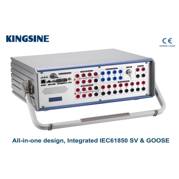
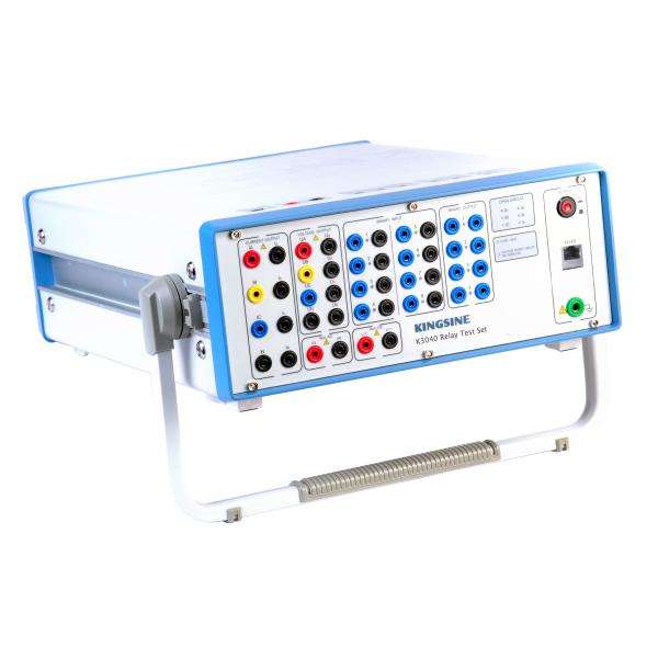
Able of what K31 series can test
Items | ANSI® No. |
IEC61850 numerical IEDs relay & merge unit | |
Distance protection relay | 21 |
Synchronising or synchronism-check relays | 25 |
Undervoltage relays | 27 |
Directional Power relays | 32 |
Undercurrent or underpower relays | 37 |
Negative sequence overcurrent relays | 46 |
Overcurrent/ground fault relays | 50 |
Inverse time overcurrent/ground fault relays | 51 |
Power factor relays | 55 |
Overvoltage relays | 59 |
Voltage or current balance relays | 60 |
Directional overcurrent relays | 67 |
Directional ground fault relays | 67N |
DC overcurrent relays | 76 |
Phase-angle measuring or out-of-step protection relays | 78 |
Automatic reclosing devices | 79 |
Frequency relays | 81 |
Motor overload protection relays | 86 |
Differential protection relays | 87 |
Directional voltage relays | 91 |
Voltage and power directional relays | 92 |
Tripping relays | 94 |
Voltage regulating relays | |
Overimpedance relays, Z> | |
Underimpedance relays, Z | |
Time-delay relays | |
Characteristic
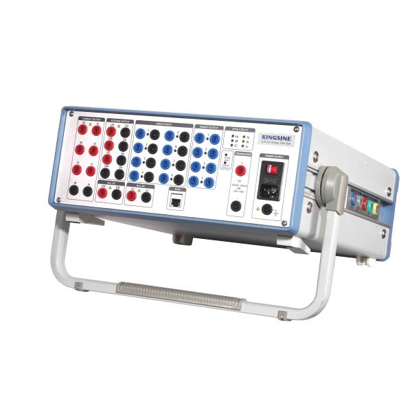
- 10 Channels (6x32A & 4x310V) outputs, Each output channels are independent and simultaneous control of magnitude, Phase angle and frequency values, able to inject DC, AC sine wave and up to 20x harmonics.
- Variable battery simulator, DC 0-350V, 140Watts max.
- 13 Low-level channels outputs up to 8Vac/10Vdc max.
- 0-600V / 0-5A AC/DC measurement in 0.1 class.
- Graphical test modules and templates for testing of various relays
- Quick relay testing facility in Manual mode
- Shot/Search/Check, Point & Click testing
- RIO/XRIO import & export facility
- Switch on to fault test(SOTF)
- Power system model for dynamic testing
- Inbuilt GPS and IRIG-B sync end-to-end testing
- Online Vector display
- Automatic test results assume
- Automatic test report creation
- Anti-clipping detect, Wrong wiring connect alarm and self-protect, overload and overheat protection

Transducer module use for testing standard and multi-function single and three phase electric power transducer

Fig Transducer calibration software interface
Parameter Setting
Transducer property setting, select parameter/ test object, find below Fig 
Fig Testing object
Enter into transducer property setting interface, set the relative setting according to the manufacturer parameter of tested transducer.

Fig Parameter setting

Fig Parameter setting
In the transducer testing view, enter setting selection, select measure quantity through the output type of tested transducer, test method can be selected freely by testing.
Test Procedure
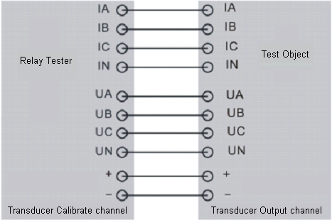
1) Test Connection

Fig Testing connection
Above testing connection use power transducer of example for explanation, other type transducer connection will regard the manufacturer` s request as standard.
2) Testing Procedure
Follow above requested to completely Set testing parameter and connection, add test point, start to test, test device calculate error automatically according sampling value