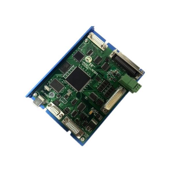
Please read this section carefully before installing and using the DLC2-PCIE control card. If you have any questions about this document, please contact BJJCZ.
1. Safe operation steps
● Please observe all safety instructions for lasers (including but not limited to descriptions and lasers, galvanometers and related sections in this document)
● Turn on the laser power at any time after turning on the computer power and galvanometer power. Otherwise, it may cause damage due to an uncontrollable laser beam.
We recommend that you use a shutter to avoid damage from uncontrolled lasers.
2. The security part of the customer's responsibility
● DLC2-PCIE is designed to control a laser scanning system. Therefore, all safety instructions for the laser system should be understood and implemented by the customer. The customer must strictly comply with the relevant safety instructions and be solely responsible for the safety of the laser system used.
● Security rules may vary from country to country. It is the customer's responsibility to comply with all local regulations.
● Please check carefully before running the software. A software error may cause the system to stop responding. In this case, the galvanometer and laser are uncontrollable.
● Please avoid damage to the board caused by moisture, dust, corrosives and foreign objects
● When storing and using the board, please avoid electromagnetic field and static electricity damage. They can damage the electronics on the board. Use an ESD bag to store the card; wear a well-grounded ESD-preventive glove contact card.
● Please ensure that the board is stored in the environment of -20°C to +60°C. The permissible operating ambient temperature is 25°C±10°C.
1. Overview
The DLC2-PCIE dedicated marking control card is a 2D/3D control card specially developed for fiber lasers. It is connected to the computer motherboard by PCIE interface.
J16: galvanometer signal, DB15
J7: Laser control interface, DB25
J17: IO/Mark on the fly Universal IO port and flight marking
The front of the board is printed with the words "DLC2-PCIE_V2"
● Output FIBER laser control signal with DB25 socket
● The galvanometer control signal is a digital signal, which can be directly connected to the internationally accepted digital galvanometer.
Pin | Name | Description |
1,9 | CLK-/ CLK+ | Clock signal - / clock signal + |
2,10 | SYNC-/ SYNC+ | Sync signal - / sync signal + |
3,11 | X Channel-/ X Channel+ | Galvanometer X signal - / galvanometer X signal + |
4,12 | Y Channel-/ Y Channel+ | Galvanometer Y signal - / galvanometer Y signal + |
5,13 | Z Channel-/ Z Channel+ | Galvanometer Z signal - / galvanometer Z signal + |
6,14 | Status- / Status+ | Reserved |
7 | NULL | Reserved |
8,15 | GND | Ground |