laser direct imaging (LDI) system solutions HDI PCB
LDI is used for imaging requirements for HDI PCB mass production
In order to meet the requirements of HDI PCB mass production, the imaging method shall:
While achieving a low defect rate and high output, it can achieve the stable production of HDI PCB conventional high-precision operation. For example:
* Advanced mobile phone board, CSP pitch less than 0.5mm (with or without wires between BGA pads)
* The plate structure is 3 + N + 3, and there are stacked via hole.
In terms of imaging, such designs require a ring width of less than 75μm. In some cases, the ring width is even less than 50μm. Due to the alignment problem, these inevitably lead to low output. In addition, driven by miniaturization, the lines and spacing are becoming thinner and thinner - meeting this challenge requires changing the traditional imaging methods.
This can be done by reducing the panel size or use a shutter exposure machine for panel imaging in several steps (four or six). Both methods achieve better alignment by reducing the influence of material deformation. Changing the panel size leads to high material costs, and using the shutter exposure machine leads to low production every day. Neither method can completely solve the material deformation and reduce the defects related to the photographic film, including the actual deformation of the photographic film when printing batch boards.
PCB laser direct imaging (LDI)
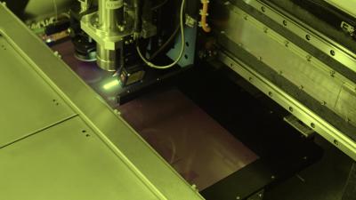
When fabricating a circuit board, the circuit traces are defined by what is the imaging process. Laser direct imaging ( LDI ) exposes the traces directly with a highly focused laser beam that in NC controlled, instead of flooded light passing through a photo tool, a laser beam will digitally create the image.
How does laser direct imaging ( LDI ) work?
Laser direct imaging needs a PCB with the photo-sensitive surface that is positioned under a computer controlled laser. And then the computer is creating the image on the board with the light of laser. A computer scans the board surface into a raster image, matching the raster image to a pre-loaded CAD or CAM design file that includes the specifications for the necessary image intended for the board, the laser is used for directly creating the image on the board.
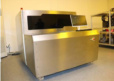
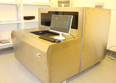
Specification/model | DPX230 |
Application | PCB,HDI,FPC (inner layer,outer layer,anti-welding) |
Resolution (mass production) | 30um |
Capacity | 30-40S@18"*24" |
Exposure Size | 610*710mm |
Panel thickness | 0.05mm-3.5mm |
Alignment Mode | UV-Mark |
Alignment capability | Outer layer±12um;Inner laye±24um |
Line width tolerance | ±10% |
Deviation increase and decrease mode | Fixed increase and contraction, automatic increase and contraction, interval increase and contraction, partition alignment |
Laser type | LD Laser,405±5nm |
File format | Gerber 274X;ODB++ |
Power | 380V three-phase alternating current, 6.4kW,50HZ, voltage fluctuation range + 7% ~-10% |
Condition | Yellow light room; Temperature 22°C ± 1°C; Humidity 50% ± 5%; Cleanliness level 10000 and above; Vibration requirements to avoid violent vibration near the equipment |
About us
We are an innovative supplier of various PCB laser direct imaging (LDI) system solutions. Our system product portfolio ranges from LDI system configurations for high-mix and emerging PCB niche applications to fully automated LDI system solutions for mass production environments.