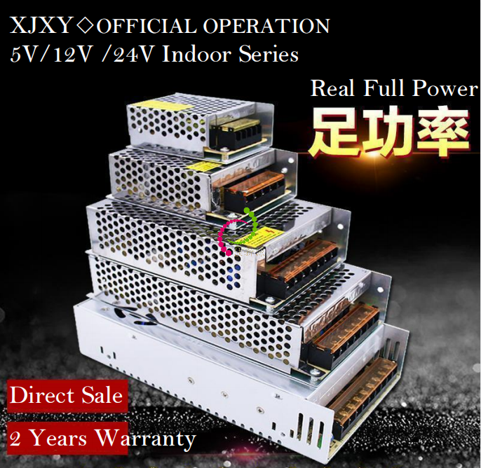
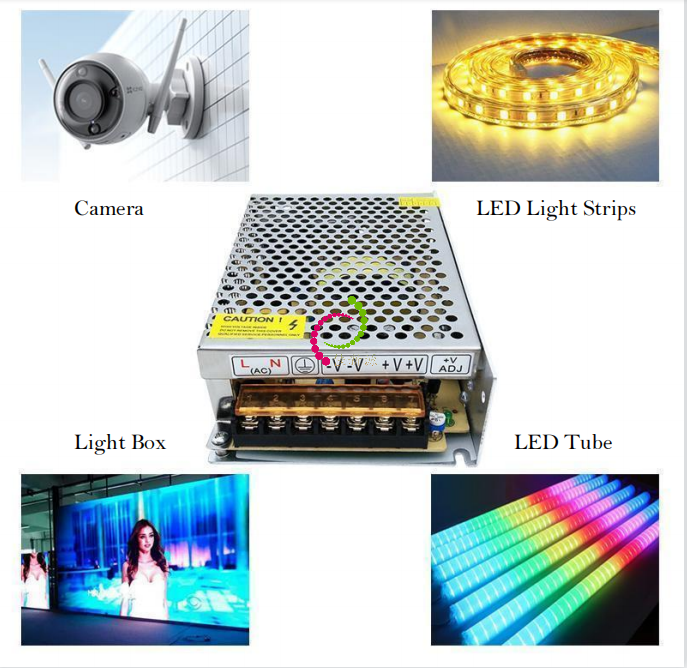
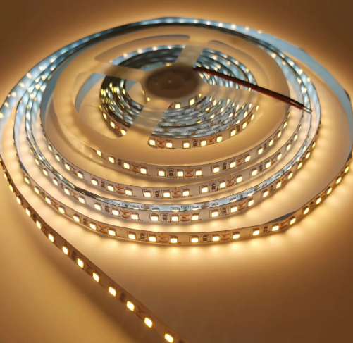
24V 120W 5A LED Driver Indoor LED Light Strips Buried Light Box LED Power Supply
Quick Detail:
Description:
Constant voltage power supply is power circuit that controls output voltage at a constant level. It always provides a constant voltage regardless of the load and is widely used as power supply for electronic circuits.
All these products adopt PWM high-frequency pulse width modulation technology, mature standardized production, strict 100% load-carrying aging, high and low voltage impact experiments and complete test records for development & production of LED driver through strictly quality control system and highly responsible attitude, thus have a good quality feedback during application.
24V Indoor drivers types mainly have many models-24W, 48W, 50W, 60W, 72W,100W, 120W,150W, 240W, 360W,400W, 500W,600W,700W,800W,1000W etc. they are mainly used for LED light strip, module, line light, wall light, underground light, LED guardrail tube and so on
Specifications:
Series | Name | LED Driver |
|
1 | Basic info | 24V 5A 120W | |
2 | Model | S-120W-24V( indoor) | |
3 | Material | Aluminum | |
4 | Efficiency | 85% | |
5 | Rated input | 220VAC 50/60Hz | |
6 | Voltage Range | 90-250VAC | |
7 | Output Voltage | DC24V±5% | |
8 | Output Current | 5A | |
9 | Output Power | 120W | |
10 | Grade | IP20 | |
12 | Protect | Shortage/Overload | |
13 | Dimension | 19.8*9.8*4.2CM | |
14 | Weight | 510g |
Notices:
1. Input voltage should be within the specified voltage range (for examples: input voltage 220VAC).
2. Prohibited to be used in the high temperature environment, power port is the thermal vents, wind 50CM range, please do not place other objects, make sure that the power should have good thermal dissipation space environment.
3. Prohibited to install power supply in the presence of flammable materials (such as wood products, flammable plastic, etc), to stay away from petrol stations or where prohibited Fireworks.
24V LED drivers related models list:
Model | Input Voltage | Output Value | Weight/g | Size/mm |
S-24W-24V | 90-250V | 24V 1A 24W | 130 | 85*59*33 |
S-50W-24V | 90-250V | 24V 2.1A 50W | 220 | 110*78*36 |
S-60W-24V | 90-250V | 24V 2.5A 60W | 221 | 110*78*36 |
S-72W-24V | 90-250V | 24V 3A 72W | 337 | 159*98*42 |
S-120W-24V | 90-130V/170-250V | 24V 5A 120W | 510 | 198*98*42 |
S-150W-24V | 90-130V/170-250V | 24V 6.25A 150W | 530 | 198*98*42 |
S-240W-24V | 90-130V/170-250V | 24V 10A 240W | 706 | 198*109*50 |
S-360W-24V | 90-130V/170-250V | 24V 15A 360W | 810 | 214*114*50 |
S-400W-24V | 90-130V/170-250V | 24V 16.7A 400W | 810 | 214*114*50 |
S-500W-24V | 90-130V/170-250V | 24V 21A 500W Al | 935 | 220*114*58 |
S-600W-24V | 170V-250V | 24V 25A 600W Al | 1180 | 200*130*65 |
S-700W-24V | 90-130V/170-250V | 24V 29A 700W | 1185 | 200*130*65 |
S-800W-24V | 170V-250V | 24V 33A 800W Al | 1185 | 200*130*65 |
S-1000W-24V | 170V-250V | 24V 41A 1000W | 1202 | 242*125*65 |
Applications:
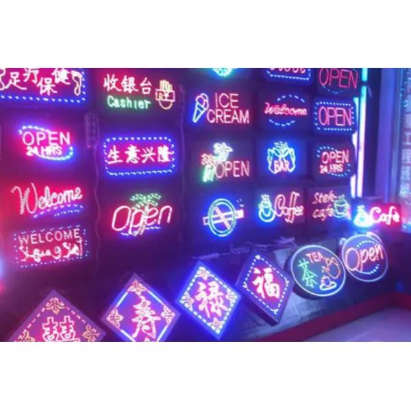
Widely used in LED Lighting, LED display, LED strips, LED advertisement screen, LED sign, LED night light, LED lamp house, LED decoration, LED wall light, LED street light , LED wall light, LED backlight, LED tube, offices , hospital , schools , factories , plants, shopping malls, supermarkets, kitchen, fair cabinet and so on.
Selection of switching power supply
Switching power supply in input anti-interference performance, due to the characteristics of its own circuit structure (multistage series), the general input interference such as surge voltage is difficult to pass, compared with linear power supply, the output voltage stability of this technical index has a greater advantage, its output voltage stability can reach (0.5~1) %. As power electronic integrated device, switching power module should pay attention to the following points in the selection.
3.1 Selection of output current
Because of the high efficiency of switching power supply, generally can reach more than 80%, so in the selection of output current, user should accurately measure or calculate the maximum absorption current of electrical equipment, in order to make the selected switching power supply have a high performance ratio, usually output calculation formula-------Is=KIf
Is - rated output current of switching power supply;
If - the maximum absorption current of the electrical equipment;
K-margin coefficient, generally 1.5 ~ 1.8;
3.2 grounding
Switching power supply will produce more interference than linear power supply, and electrical equipment sensitive to common-mode interference should take grounding and shielding measures. According to EMC restrictions such as ICE1000, EN61000 and FCC, switching power supply should take EMC measures, so switching power supply should be equipped with EMC filter.
3.3 Protection circuit
Switching power supply in design must have over current, overheating, short circuit and other protection functions, so its design should be preferred to choose switching power supply module with protection functions , and its protection circuit technical parameters should be matched with the working characteristics of the electrical equipment, in order to avoid the damage to the electrical equipment or switching power supply.
Test methods for switching power supply
1. withstand voltage testing
Definition: withstand the effective value of AC between specified terminals such as I/P-O/P, I/P-FG, O/P-FG, leakage current is generally allowed to be 10 MA and the time of 1 min.
1.2 Test conditions: Ta: 25 degrees Celsius; RH: indoor humidity.
1.3 Test circuit:
1.4 Description:
1.4.1 Voltage test is mainly to prevent electrical damage, through the input string of high voltage, affect the safety of users.
1.4.2 During the test, the voltage must be increased from 0V and reached the highest point within 1 minute.
1.4.3 Pay attention to the Timer setting of the tester when discharging, and switch the voltage back to 0V before OFF.
1.4.4 During the safety certification test, the transformer shall be separately measured. The temperature shall be 25 degrees Celsius, RH: 95 degrees Celsius, 48HR, and the transformer primary/secondary and primary /CORE shall be tested later.
1.4.5 Production line test time is 1 second.
2. Ripple noise (ripple noise voltage) testing
2.1 Definition:
Maximum (P-P) or effective value of the AC voltage component overlapped over DC output voltage.
2.2 Test conditions:
I/P: Nominal
O/P : Full Load
Ta: 25 ℃
2.3 Test circuit:
2.4 Test waveform:
2.5 Description:
2.5.1 The shorter the oscilloscope GND line, the better. The test line should be far away from the PUS.
2.5.2 Using a 1:1 Probe.
2.5.3 The Scope's BW is generally set at 20MHz, but it is better to set the BW to the maximum for the ripple noise of the current network products.
2.5.4 Noise and the use of the instrument, the environment is very different, so the test must indicate the test location.
2.5.5 Test ripple noise shall not exceed the original specification value +1%Vo.
3. Leakage current testing.
3.1 Definition:
Input the current flowing between the chassis (the chassis must be grounded).
3.2 Test conditions:
I/P: Vin Max) x 1.06 (TUV) / 60 hz
Vin max.(UL1012)/60Hz
O/P: No Load/Full Load
Ta: 25 ℃
3.3 Test circuit:
3.4 Description:
3.4.1 Both L and N need to be measured.
3.4.2 UL1012 R value is 1K5 and TUV R value is 2K/0. 15 uf.
3.4.3 Leakage current Specifications TUV: 3. 5 ma, UL1012:5 ma.