KDP06 Series Explosion Proof Electrical Equipment Explosion Proof Magnetic Starter
Application and Features:
Technical Parameter:
Ex marking | Gas | Il2 G Ex db IIB T6/T5/T4 Gb | Ex db IIB T6/T5/T4 Gb | Ex d IIB T6/T5/T4 Gb | |||||||||||
Ii2 G Ex db IIB+H2 T6/T5/T4 Gb | Ex db IIB+H2 T6/T5/T4 Gb | Ex d IIB+H2 T6/T5/T4 Gb | |||||||||||||
Dust | II2 D Ex tb IIIC T80/T95/T130℃ Db | Ex tb IIIC T80/T95/T130℃ Db | Ex tD A21 IP66 T80/T95/T130℃ | ||||||||||||
Conformity to standards | IEC 60079-0,IEC 60079-1,IEC 60079-31 EN 60079-0, EN 60079-1, EN 60079-31 GB3836.1,GB3836.2,GB12476.1,GB12476.5 | ||||||||||||||
Enclosure material | Enclosure | Aluminum alloy enclosure, powder coated, Industrial grey with dark lines texture (RAL7035) | |||||||||||||
Transparent part | Tempered glass, resistant to 4J impact | ||||||||||||||
Rain shade | Bended steel plate surface powder coated, industrial grey with dark lines texture (RAL7035) or stainless steel 304/316, please note when needed | ||||||||||||||
Exposed fasteners | Stainless steel | ||||||||||||||
Components | Power circuit breaker | Miniature circuit breaker (MCB) or molded case circuit breaker (MCCB) and leakage circuit breaker | |||||||||||||
Branch switch | Miniature circuit breaker (MCB) or molded case circuit breaker (MCCB) and leakage circuit breaker | ||||||||||||||
Terminal block | World famous brand | ||||||||||||||
Indicator | Red, green, yellow, blue, white | ||||||||||||||
Button | Red, green, yellow, blue, white | ||||||||||||||
Control switch | LW26-D, LW26-F | ||||||||||||||
AC contactor | World famous brand | ||||||||||||||
Thermal relay | World famous brand | ||||||||||||||
Rated voltage | Maximum 690V AC | ||||||||||||||
Rated current | Maximum 200A | ||||||||||||||
Frequency | 50Hz/60Hz | ||||||||||||||
Maximum dissipation power |
Enclosure size |
Type | Ta:+40℃ | Ta:+60℃ | |||||||||||
T6/T80℃ | T5/T95℃ | T4/T130℃ | T6/T80℃ | T5/T95℃ | The weight of Empty enclosure | ||||||||||
Power | Current | Power | Current | Power | Current | Power | Current | Power | Current | ||||||
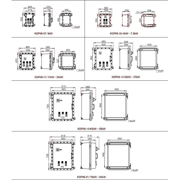
282×210×170 | 03 | 45W | -- | 110W | -- | 110W | -- | 45W | -- | 72W | -- | 9.0kg | |||
350×210×170 | 07 | 45W | ≤40A | 80W | ≤50A | 139W | -- | 45W | ≤40A | 80W | ≤50A | 11.5kg | |||
350×300×235 | 08 | 45W | ≤40A | 80W | ≤50A | 139W | -- | 45W | ≤40A | 80W | ≤50A | 16.6kg | |||
433×350×280 | 11 | 100W | ≤95A | 288W | ≤120A | 288W | -- | 100W | ≤95A | 162W | ≤120A | 26kg | |||
563×433×280 | 15 | 130W | ≤150A | 365W | ≤200A | 365W | -- | 130W | ≤150A | 225W | ≤200A | 48kg | |||
720×563×280 | 19 | 200W | ≤200A | 448W | ≤300A | 448W | ≤300A | 200W | ≤200A | 380W | ≤300A | 85kg | |||
720×563×350 | 21 | 210W | ≤200A | 690W | ≤300A | 690W | ≤300A | 210W | ≤200A | 400W | ≤300A | 95kg | |||
Degree of protection | IP66 | ||||||||||||||
Ambient temperature | -20℃~+40/60℃, -40℃~+40/60℃ | ||||||||||||||
Cable entry | M□X1.5(default, exact size according to requirement) , NPT thread (optional) | ||||||||||||||
Inlet direction | Bottom in and bottom out, upon request | ||||||||||||||
Installation method | Wall type (default) | ||||||||||||||
Stand type (optional) |
Outline and Installation Dimension(Dimensions in mm):
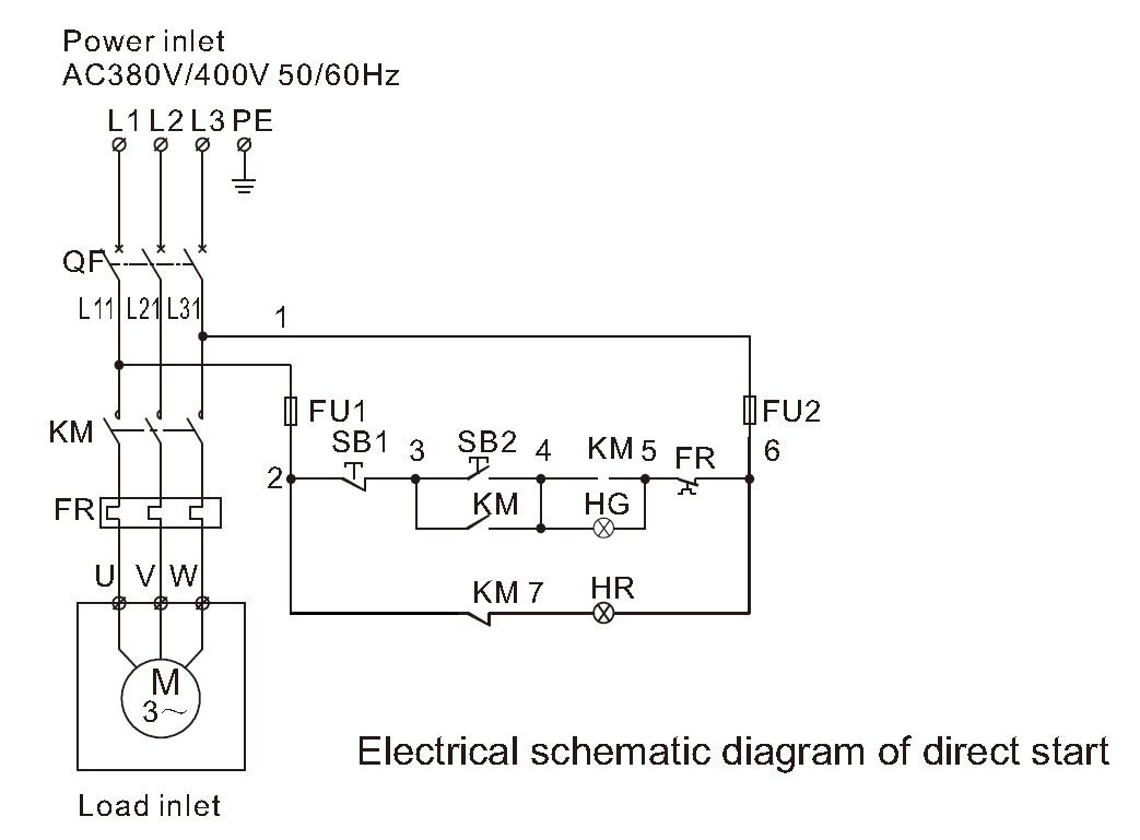
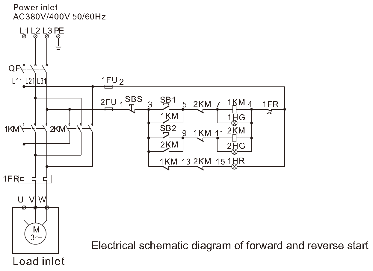
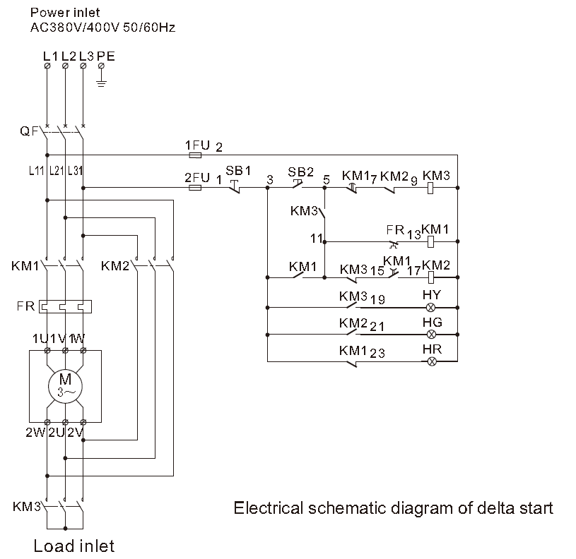
Electrical Schematic Diagram:
Description of electrical components code | |
QF | Circuit breaker |
KM | AC contactor |
FR | Thermal relay |
FU1, FU2 | Fuse |
SB1 | Stop button |
SB2 | Start button |
HR | Stop indicator |
HG | Run indicator |
Description of electrical components code | |
QF | Circuit breaker |
KM1, KM2 | AC contactor |
FR | Thermal relay |
FU1, FU2 | Fuse |
SBS | Stop button |
SB1 | Forward start button |
SB2 | Reverse start button |
HR | Stop indicator |
HG1 | Forward running indicator |
HG2 | Reverse running indicator |