2V 350MA 0.81W 2720 33-97LM 612-630NM SMD LED CHIP FOE AUTOMOTIVE LIGHTING
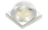
2720 is a very powerful and reliable LED packaging product. Its outstanding advantages are high brightness, low thermal resistance and good thermal stability. Unique temperature cycle stability. The lead frame part is optimized for the thermal expansion coefficient of the circuit board to ensure the high stability of the welding point.
Package: SMD epoxy resin package
Typical radiation: 120 °
Corrosion resistance grade: 3B
Automobile certification: iec60810, aec-q102
ESD level 3b, 2 kV, 2 kV
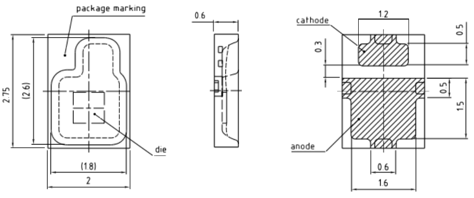
Dimensions: 2.75 x 2.0 x 0.6 mm
mall size (especially height)
The best thermal resistance grade is suitable for medium power devices
Panchromatic spectrum
8-color options, high overall performance
Strong flexibility and free design
The first product on the market to realize multiple power levels in one package size
The industry's most experienced in a package size solution
The two colors of red and super red have dual functions of separation
Internal lighting (as shown in the environment diagram)
signal
night vision
LED head up display system and laser
Maximum Ratings
Parameter Symbol Values
Operating Temperature Top min. max. | -40 °C 125 °C |
Storage Temperature Tstg min. max. | -40 °C 125 °C |
Junction Temperature Tj max. | 150 °C |
Junction Temperature for short time applications* Tj max. | 175 °C |
Forward current IF min. T = 25 °C max. | 10 mA 500 mA |
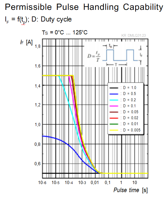
Surge Current IFS max. t ≤ 10 µs; D = 0.005 ; TS = 25 °C | 1500 mA |
Reverse voltage 2): VR VR max. T = 25 °C | 12 V |
ESD withstand voltage acc. to ANSI/ESDA/JEDEC JS-001 (HBM, Class 2) VESD | 2 kV |
The median lifetime (L70/B50) for Tj = 175°C is 100h.
Characteristics
IF 350 mA; TS = 25 °C
Parameter Symbol Values
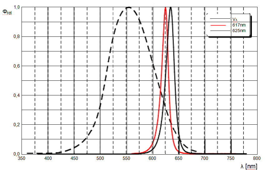
Peak Wavelength | λpeak typ. 630 nm |
Dominant Wavelength 3) IF = 350 mA | min. 612 nm λdom typ. 621 nm max. 630 nm |
Spectral Bandwidth at 50% Irel,max | ∆λ typ. 18 nm |
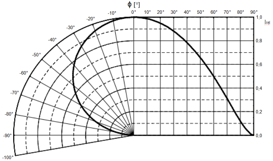
Viewing angle at 50% Iv | 2φ typ. 120 ° |
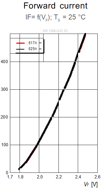
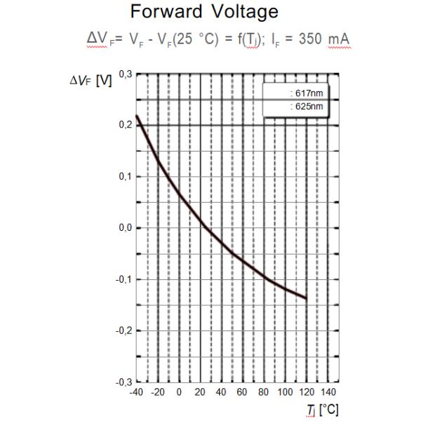
Forward Voltage 4) IF = 350 mA | min. 2.0 v VF typ. 2.3 v max. 2.6 v |
Reverse current 2) VR = 12 V | IR typ. 0.01 µA max. 10 µA |
Real thermal resistance junction/solderpoint 5) | Rthjs real typ. 13.0 K / W max. 16.0 K / W |
Electrical thermal resistance junction/solderpoint 5) with efficiency ηe = 30 % | Rthjs elec typ. 9.1 K / W max. 11.2 K / W |
Brightness
Groups
Group
Luminous Flux 1
I = 350 mA
33 lm | 39 lm | 12 cd |
39 lm | 45 lm | 14 cd |
45 lm | 52 lm | 16 cd |
52 lm | 61 lm | 19 cd |
61 lm | 71 lm | 22 cd |
71 lm | 82 lm | 25 cd |
82 lm | 97 lm | 30 cd |
2.00 V | 2.15 V |
2.15 V | 2.30 V |
2.30 V | 2.45 V |
2.45 V | 2.60 V |
Wavelength Groups
Group
Dominant Wavelength 3)
IF = 350 mA
612 nm | 616 nm |
616 nm | 620 nm |
620 nm | 624 nm |
624 nm | 627 nm |
627 nm | 630 nm |
Relative Spectral Emission
Φrel = f (λ); IF = 350 mA; TS = 25 °C
Radiation Characteristics
= f (ϕ); S 25 °C
Dimensional Drawing
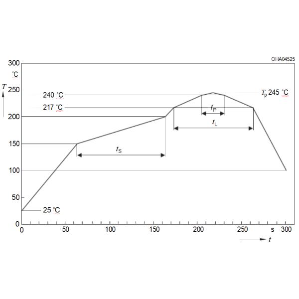
Reflow Soldering Profile
Product complies to MSL Level 2 acc. to JEDEC J-STD-020E
Profile Feature Symbol Pb-Free (SnAgCu) Assembly Unit
Minimum Recommendation Maximum
Ramp-up rate to preheat*) 2 25 °C to 150 °C | 3 | K/s | ||
tS 60 100 T to T | 120 | s | ||
| 3 | K/s | ||
Liquidus temperature T 217 | °C | |||
Time above liquidus temperature tL 80 | 100 | s | ||
Peak temperature T 245 | 260 | °C | ||
Time within 5 °C of the specified peak temperature TP - 5 K | 30 | s | ||
Ramp-down rate* 3 T to 100 °C | 6 | K/s | ||
Time 25 °C to TP | 480 | s |
All temperatures refer to the center of the package, measured on the top of the component * slope calculation DT/Dt: Dt max. 5 s; fulfillment for the whole T-range