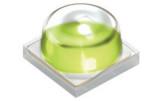
3V 700MA 2W CERAMIC3030 40-50LM 440-460NM SMD LED CHIP FOR PLANT LIGHTING
Characteristic
Parameter Symbol Values
Operating Temperature | T op | min. max. | -40 °C 120 °C |
Storage Temperature | T stg | min. max. | -40 °C 120 °C |
Junction Temperature | T | max. | 135 °C |
Junction Temperature absolute* | Tjabs | max. | 150 °C |
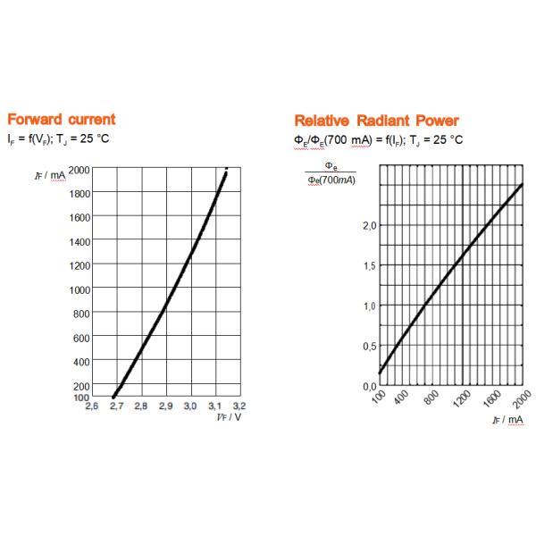
Forward current | I | min. max. | 100 mA 2000 mA |
Surge Current t ≤ 10 µs; D = 0.005 %; TJ = 25 °C | FS | max. | 2000 mA |
Reverse voltage 2) | V | Not designed for reverse operation | |
ESD withstand voltage acc. to ANSI/ESDA/JEDEC JS-001 (HBM, Class 3B) | ESD | 8 kV |
This is verified by testing 30 pieces. Pass criteria: No catastrophic failures allowed, luminous flux must be better than L70B50 after 1000 h.
Characteristics
I = 700 mA; TJ = 25 °C
Parameter Symbol Values
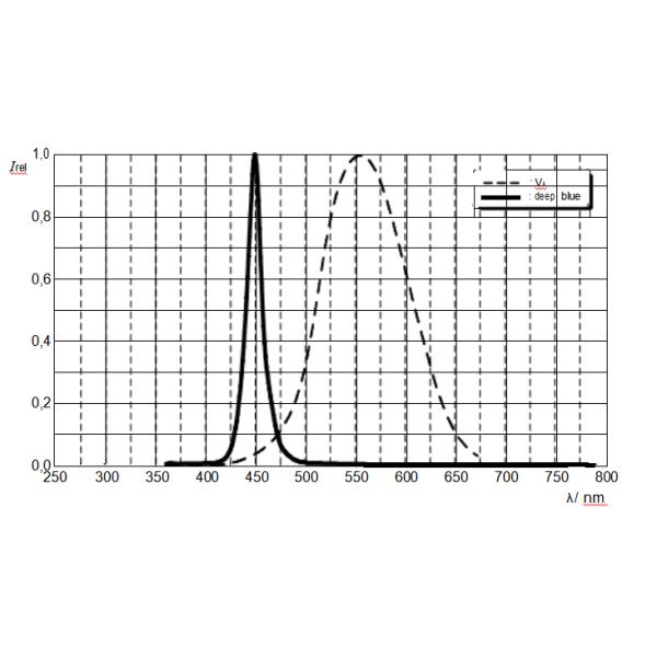
Peak Wavelength | λpeak typ. 445 nm |
Dominant Wavelength 3) I = 700 mA | min. 444 nm typ. 450 nm max. 457 nm |
Spectral Bandwidth at rel,max | ∆λ typ. 18 nm |
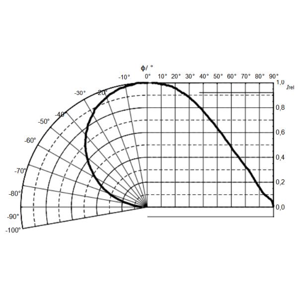
Viewing angle at 50% IV | 2φ typ. 120 ° |
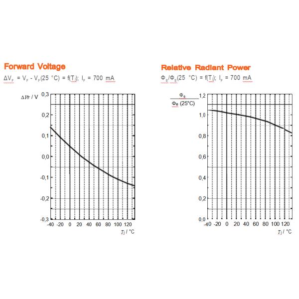
Forward Voltage 4) I = 700 mA | VF min. 2.80 V typ. 2.90 V max. 3.20 V |
Reverse current 2) | IR Not designed for reverse operation |
Electrical thermal resistance junction/solderpoint with efficiency ηe = 65 % | RthJS elec. typ. 1.3 K / W |
Forward Voltage Groups
Group Forward Voltage 4)
I = 700 mA
VF:
2.8v | 2.9v |
2.9v | 3.0v |
3.0v | 3.1v |
3.1v | 3.2v |
Wavelength
Group
Dominant Wavelength 3)
I = 700 mA
λdom
444nm | 449nm |
449nm | 453nm |
453nm | 457nm |
Relative Spectral Emission
Irel = f (λ); IF = 700 mA; TJ = 25 °C
Radiation Characteristics
Irel = f (ϕ); TJ = 25 °C
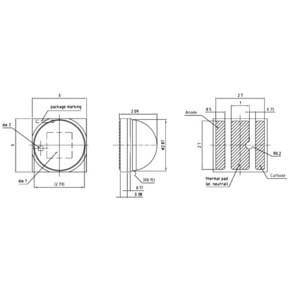
Dimensional Drawing
Further Information: 29.0 mg
Approximate Weight: Package marking: Cathode
Corrosion test: Class: 3B
Test condition: 40°C / 90 % RH / 15 ppm H2S / 14 days (stricter than IEC 60068-2-43)
ESD advice: The device is protected by ESD device which is connected in parallel to the Chip.
Reflow Soldering Profile
Product complies to MSL Level 2 acc. to JEDEC J-STD-020E
Profile Feature Symbol Pb-Free (SnAgCu) Assembly Unit
Minimum Recommendation Maximum
Ramp-up rate to preheat*) 2 25 °C to 150 °C | 3 | K/s |
tS 60 100 T to T | 120 | s |
Ramp-up rate to peak*) 2 T to T | 3 | K/s |
Liquidus temperature TL 217 | °C | |
Time above liquidus temperature tL 80 | 100 | s |
Peak temperature T 245 | 260 | °C |
Time within 5 °C of the specified peak 10 20 temperature TP - 5 K | 30 | s |
Ramp-down rate* 3 T to 100 °C | 6 | K/s |
Time 25 °C to TP | 480 | s |
All temperatures refer to the center of the package, measured on the top of the component * slope calculation DT/Dt: Dt max. 5 s; fulfillment for the whole T-