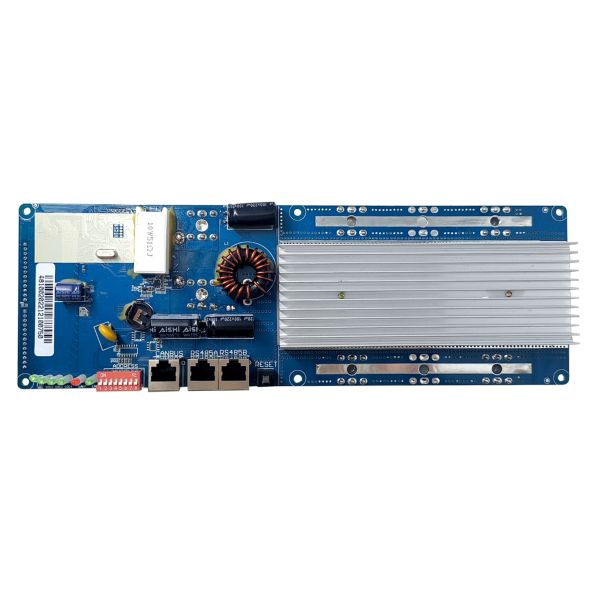
FEATURES
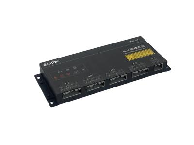
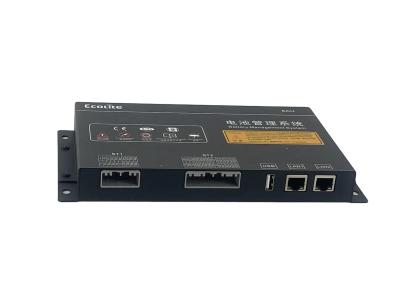
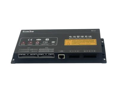
The BMS battery system is commonly known as a battery butler. Its main function is to intelligently manage and maintain each battery unit, monitor the battery status, prevent the battery from overcharging and over-discharging, and extend the battery life.
Technical parameters | |||||||
Function | Test project | Specifications | Unit | ||||
Min | Typical values | Max | |||||
Charging protection | Overcharge protection voltage | 3.85 | 3.90 | 3.95 | V | ||
Overcharge protection delay time | 800.00 | 1000.00 | 1400.00 | mS | |||
Overcharge protection restores voltage | 3.75 | 3.80 | 3.85 | V | |||
Discharge protection | Overdischarge protection voltage | 1.95 | 2.00 | 2.05 | V | ||
Overdischarge protection delay time | 800.00 | 1000.00 | 1400.00 | mS | |||
Overdischarge protection restores voltage | 2.35 | 2.40 | 2.45 | V |
Technical parameters | |||||||
Function | Test project | Specifications | Unit | ||||
Min | Typical values | Max | |||||
Overcurrent protection | Charging overcurrent protection value | / | / | / | A | ||
Charging overcurrent delay | / | / | / | mS | |||
Charging overcurent release recovery conditions | Disconnect the charger | ||||||
Discharge overcurrent 1 protection value | 475 | 500 | 525 | A | |||
Discharge overcurrent 1 protection delay | 640 | 700 | 825 | mS | |||
Discharge overcurrent protection value 2 | 950 | 1000 | 1050 | A | |||
Discharge overcurrent 2 protection delay | 78 | 90 | 105 | mS | |||
Recovery conditions for discharge overcurrent protection | Disconnect load |
Technical parameters | |||||||
Function | Test project | Specifications | Unit | ||||
Min | Typical values | Max | |||||
Short circuit protection | Short circuit protection delay time | 220 | 400 | 610 | uS | ||
Short circuit protection recovery | Disconnect load |
Technical parameters | |||||||
Function | Test project | Specifications | Unit | ||||
Min | Typical values | Max | |||||
Balance function | Balanced turn-on voltage | / | 3.60 | / | V | ||
Balanced shutdown voltage | / | 3.59 | / | V | |||
Equilibrium mode | Passive equilibrium | ||||||
Equalizing current | 15 | 20 | 25 | mA |
Technical parameters | |||||||
Function | Test project | Specifications | Unit | ||||
Min | Typical values | Max | |||||
Temperature protection | Charging high temperature protection value | 72 | 75 | 78 | ℃ | ||
Charging high temperature protection release value | 65 | 70 | 75 | ℃ | |||
Low temperature protection value for charging | -13 | -10 | -7 | ℃ | |||
Low temperature protection release value during charging | / | -9 | / | ℃ | |||
High temperature protection value for discharge | 72 | 75 | 78 | ℃ | |||
Discharge high temperature protection release value | 65 | 70 | 75 | ℃ | |||
MOS over temperature protection value | 87 | 90 | 93 | ℃ | |||
MOS over temperature recovery value | 80 | 85 | 90 | ℃ |
Technical parameters | |||||||
Function | Test project | Specifications | Unit | ||||
Min | Typical values | Max | |||||
Self consumption power | Working mode | / | / | 220 | uA | ||
Operation temperature | Normal working range | -40 | / | 95 | ℃ | ||
Size(L*W*D) | 146mm*50mm*15mm |
Product wiring diagram
Q: Do you provide free sample?