1.S9-M series full sealed NLTC oil immersed 10kv 400kva power distribution transformer
(1)The iron core
The core is made of cold rolled grain oriented silicon steel with high electrical conductivity and has inclined joint lamination structure. The cross section of the wick is a ladder circle, consistent with the cross section of the yoke.
(2)winding
The windings are corrugated non-oil-adhering air ducts and bound with shrinkable tape; All windings are concentric coils; The tap of the high voltage winding of the tap voltage is led to the tap changer which is mounted on the box cover. When changing the tap voltage, the power supply must be cut off first.
(3)Installation of protective devices
Transformers of all capacity specifications are equipped with pressure relief valves.
Gas relays with alarm and trip terminals are available upon request.
(4)Oil temperature measurement division
All transformers are equipped with a glass rod thermometer tube holder, which is set at the top of the tank and immersed in about 120±10mm of oil
1000-2000kVA transformer equipped with outdoor signal thermometer
(5)Transformer oil tank
Transformer tank is corrugated wall, surface powder, with film reinforcement. Corrugated heat sink not only has cooling function, but also has a "breathing" function. The elasticity of corrugated heat sink enables it to adapt to changes in the amount of oil caused by temperature changes. Therefore, this seal does not protect the device, reducing the height of the transformer.
Transformer in the packaging process using vacuum oil injection technology, completely remove the transformer water, so that the transformer oil does not contact with air. The technology also avoids the degradation of insulation performance or oil aging due to oxygen or moisture entry, and improves the operational reliability of the transformer.
2.Main Technical Parameters
Main Technical Parameters for 10KV level S9-M,S10-M,S11- M Series three-phase full-sealed non-excitation-tap-changing distribbution transformer | ||||||||||||
Rated Power (kva) | High Voltage (kv) | H.V.Tap range | Low Voltage (kv) | Connection symbol | Short Circuit Impendence (%) | No-load loss(W) | On-load loss(W) | No load current (%) | ||||
S9 | S10 | S11 | S9 | S10 | S11 | |||||||
30 | 6 6.3 10 10.5 11 | ±5% ±2x2.5% | 0.4 | Dyn11 Yyn0 | 4 | 130 | 110 | 100 | 600 | 600 | 600 | 2.1 |
50 | 170 | 150 | 130 | 870 | 870 | 870 | 2 | |||||
63 | 200 | 180 | 150 | 1040 | 1040 | 1040 | 1.9 | |||||
80 | 250 | 200 | 180 | 1250 | 1250 | 1250 | 1.8 | |||||
100 | 290 | 230 | 200 | 1500 | 1500 | 1500 | 1.6 | |||||
125 | 340 | 270 | 240 | 1800 | 1800 | 1800 | 1.5 | |||||
160 | 400 | 310 | 280 | 2200 | 2200 | 2200 | 1.4 | |||||
200 | 480 | 380 | 340 | 2600 | 2600 | 2600 | 1.2 | |||||
250 | 560 | 460 | 400 | 3050 | 3050 | 3050 | 1.2 | |||||
315 | 670 | 540 | 480 | 3650 | 3650 | 3650 | 1.1 | |||||
400 | 800 | 650 | 570 | 4300 | 4300 | 4300 | 1 | |||||
500 | 960 | 780 | 680 | 5150 | 5150 | 5150 | 1 | |||||
630 | 4.5 | 1200 | 920 | 810 | 6200 | 6200 | 6200 | 0.9 | ||||
800 | 1400 | 1120 | 980 | 7500 | 7500 | 7500 | 0.8 | |||||
1000 | 1700 | 1320 | 1150 | 10300 | 10300 | 10300 | 0.7 | |||||
1250 | 1950 | 1560 | 1360 | 12000 | 12000 | 12000 | 0.6 | |||||
1600 | 2400 | 1880 | 1640 | 14500 | 14500 | 14500 | 0.6 | |||||
2000 | 5 | 2830 | 2270 | 1940 | 17140 | 17140 | 17140 | 0.6 | ||||
2500 | 3350 | 2690 | 2300 | 20260 | 20260 | 20260 | 0.5 |
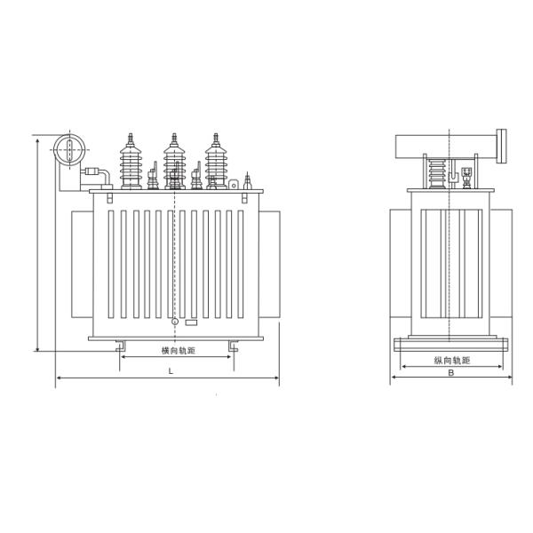
3.Technical drawings
4. FAQ
1. Send the technical data, better for all useful information; we will make a good recommendation.
If possible please attach one reference picture to avoid any misunderstanding or any links from our website for we get a better understanding.
2. The lead time depend on quantity of order. Some standard type is on stock. Otherwise, it will take 3-15 days.
3. Usually shipped by sea, small order or urgent order we can send you by air.
4. All our activities are accredited to ISO 14001:2015 and IEC standard.
5. Technology ensure the quality satisfy international request.