Application water pump model pairing table
Model | D1 | D2 | D7 | M | L | L1 | L3 |
GLF - 12 | 12 | 25 | 29 | M28*1.5 | 55 | 49 | 30 |
GLF - 16 | 16 | 30.5 | 34 | M33*1.5 | 57.5 | 51 | 30.5 |
GLF - 22 | 22 | 39.5 | 50 | M49*1.5 | 72 | 55 | 35.0 |
Technical Parameters
Temperature | -30℃~+200℃ |
pressure | ≤1.2Mp a |
Speed | ≤10m/s |
Medium | Acid, alkali, below medium corrosive liquid |
Materials
Rotary Ring | SiC/VIT |
Stationary Ring | Carbon/SiC/TC |
Spring | SUS304/SUS316 |
Stationary Seat | SUS304/SUS316 |
Secondary Seal | Fkm |
Rotary Ring Holder | SUS304/SUS316 |
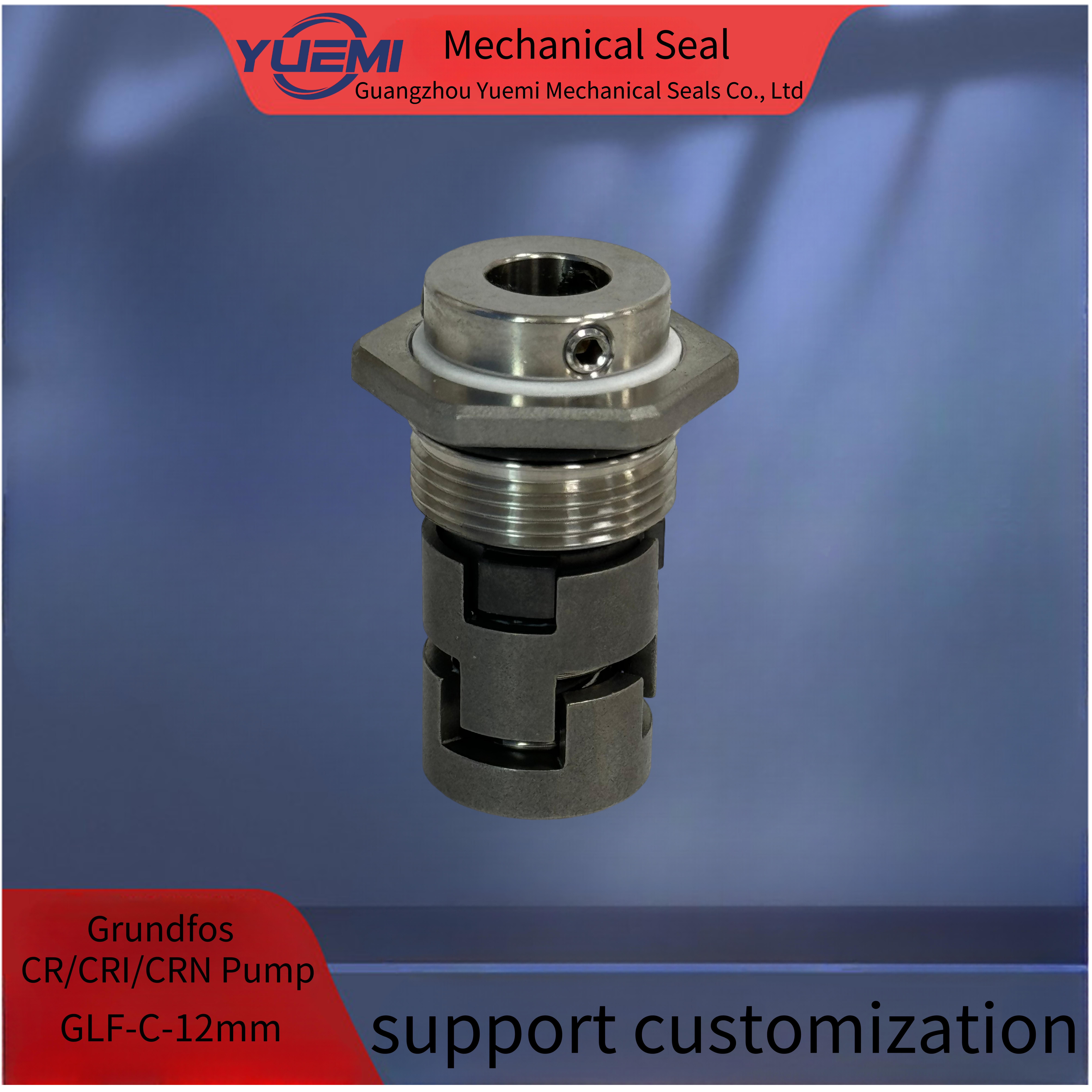
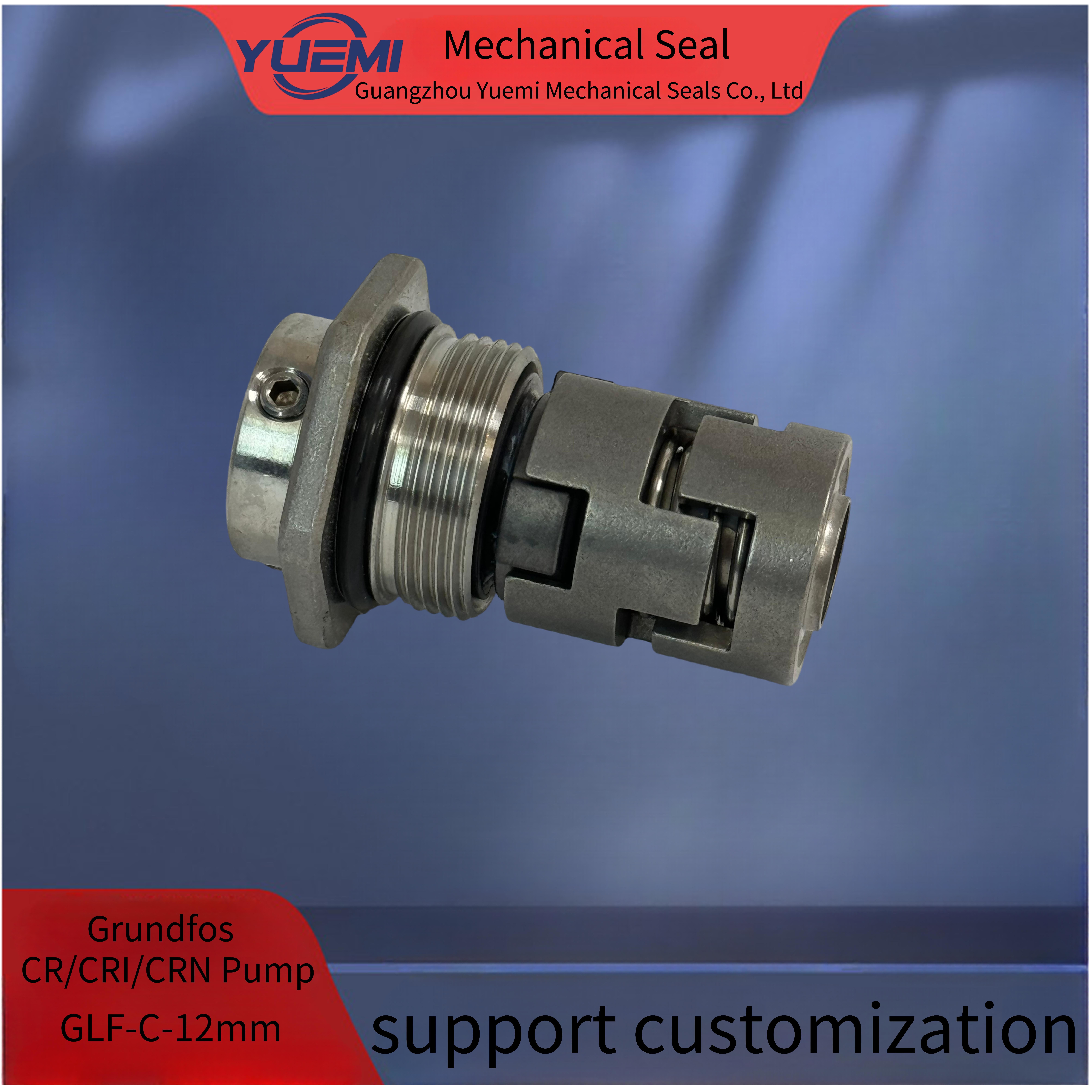
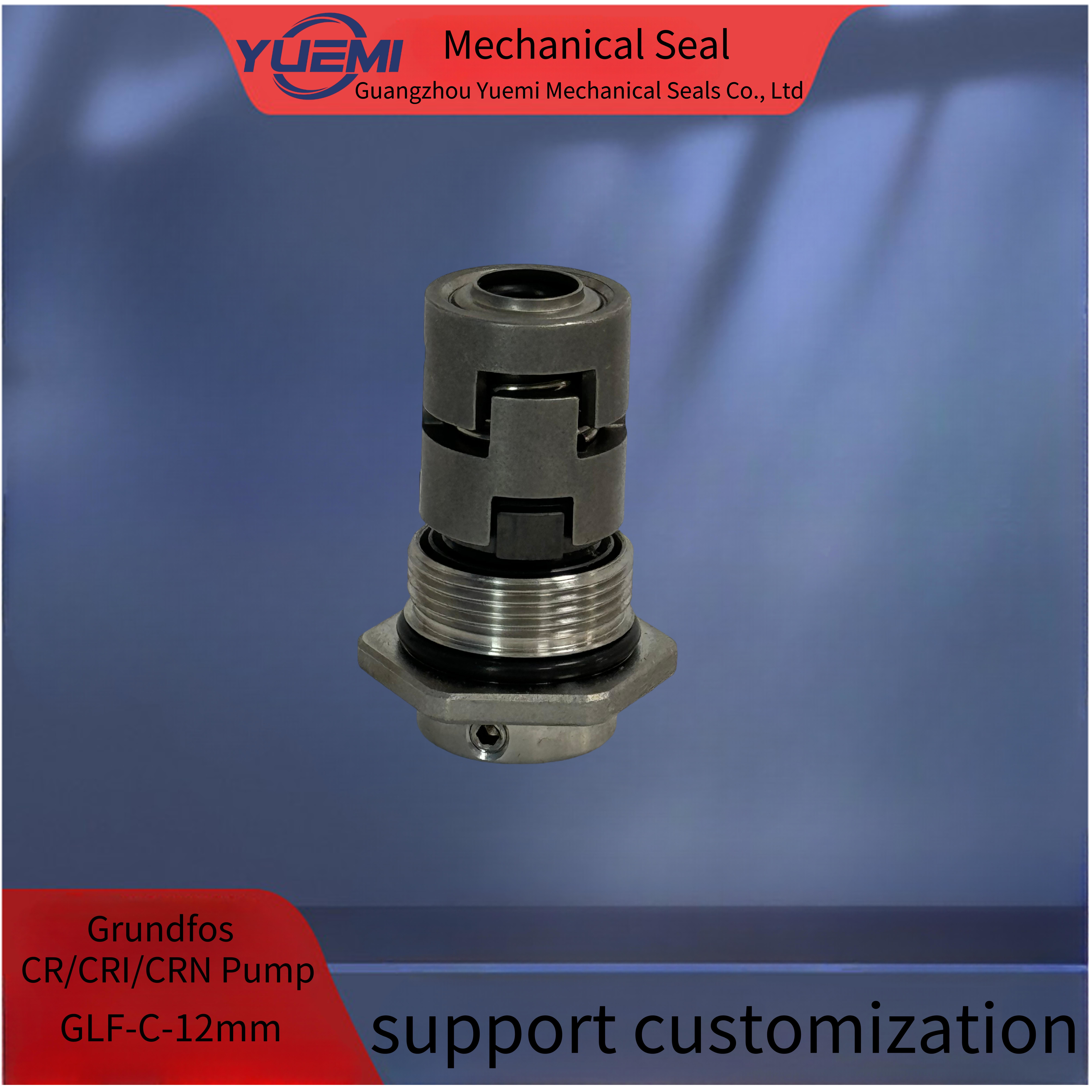
Mechanical Seal For Grondfos Pump Seal GLF 12MM.16MM,22MM Cartridge Mechanical Seal
Description:
Gr0ndf0s CR Replacement Cartridge Mechanical Seals
Standard Shaft Size:12mm,16mm,22mm
Operating Range:
Cartridge Pump Seal for Grondfos(mechanical seal, pump seal)
Description:
Equivalent with type H.
Shaft size: 12MM,16MM,22MM
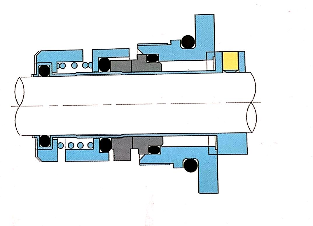
Balanced, cartridge O-ring seal unit with rigid torque transmission system
This seal type is assembled in a cartridge unit which makes replacement safe and easy.
Similar to the type D seal, the balancing makes this O-ring seal type suitable for high-pressure applications.
Gr0nd0s Replacement Cartridge Mechanical Seals
Gr0nd0s CR1, CR3, CR5 - 12mm
OEM Part Numbers: 96455082, 96455086, 96455083, 96455087, 96455085
Gr0nd0sCR10, CR15, CR20 - 16mm
OEM Part Numbers: 96511836, 96511840, 96511837, 96511845, 96511841
Gr0nd0s CR32, CR35, CR64, CR90 - 22mm
OEM Part Numbers: 96416584, 96433365, 96525459, 96525490, 96436728
MATERIALS: Silicon vs Silicon Carbide EPDM elastimers
OEM Part Numbers
Seal Material: Sic/Sic/EPDM
Seal Type: Grondfos Cartridge
Preperation:
1. Shaft Outside Diameter is within tolerance +-0.05mm
2. Shaft run out <0.1mm
3. Shaf end float <0.13mm
4, No sharp edges on the shaft over the o ring
Note:
During the installation,don't scratch or damage the o ring.lf anything is damaged,please contactwith Us to replace a new one.
Installation in strucstions:
1. The full set of cartridge seal is cleaned and exactly passed leakage examine before sale.Inorder to avoid damage,don't disassemble and clean the parts again before fixing.
2 The fitting allowance between the seal and shaft is dl h6 0.8,and there should be leading-inedge at the end of shaft.The outside diameter of shaft at the position of screw should be 01 0.2mm smaller,resisting the screw over-tighten.Lubricate the shaft with oil
3. Place the cartridge seal into the pump chamber,then:
A: Tighter four screw bolts of flanges,ensuring the medium leading in hole"G"at the top Position
B : Tighter four set screws and position the shaft sleeve on the shaft.
C: Remove four gauge plates.Please keep them and they wil be used in future installation and
disassemble.
D: Connect the medium lead_in pipe with hole"G"in order to flush away the friction heat and
flushing the seal chamber when pump running.
Note:
ter complete the installation,turning the shaft by hand to check for the rotationi he shat could not rotate smoothily,seal had been improperly installed.
We would like lo sincerely ooperale with Clients to supply high qually products and senice We beleve in establishing a long:erm cooperalive relalionshipis lhe key to suceess