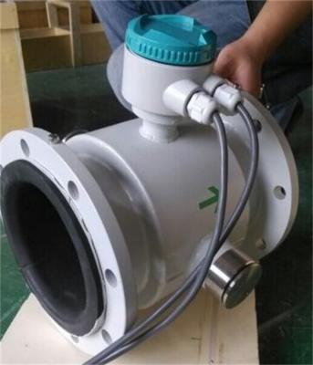
Specifications
Brand Name :
BEITE
Certification :
CE ISO
Place of Origin :
CHINA
MOQ :
1 Piece/Pieces
Price :
Negotiate
Payment Terms :
T/T, Western Union
Supply Ability :
sufficient goods
Delivery Time :
5 working days after payment
Packaging Details :
carton or customers requests available
Range ratio :
1:30(0.5m/s~15m/s)
Applicable medium :
liquid
Display mode :
Liquid crystal display
Maximum velocity :
15m/s
Nominal pressure :
0.6~4 Mpa
Nominal diameter :
3~3000
Description

Electromagnetic flowmeter is a flow measurement instrument based on Faraday's electromagnetic induction principle, and is often used to measure the flow of conductive liquids or slurries. Its working principle is mainly based on the law of electromagnetic induction, and the specific process is as follows:

1. **Principle of electromagnetic induction**:
According to Faraday's law of electromagnetic induction, when a conductive fluid flows through a uniform magnetic field, the charged particles in the fluid will generate an electromotive force (i.e., induced voltage) under the action of the magnetic field. This electromotive force is related to factors such as the flow rate of the fluid, the strength of the magnetic field, and the inner diameter of the pipe.

2. **Structural composition**:
- **Magnet**: used to generate a constant magnetic field.
- **Electrodes**: located on both sides of the pipe of the flowmeter, used to measure the induced voltage generated in the fluid.
- **Pipeline**: The pipe through which the fluid passes, usually made of insulating material to ensure that it does not affect the electric field.
- **Signal processor**: used to convert the induced voltage into a flow signal.

3. **Working process**:
- The electromagnetic flowmeter conducts current through the fluid in the pipe, and the magnet generates a magnetic field perpendicular to the flow direction outside the pipe where the fluid flows.
- When the fluid flows through the magnetic field, according to Faraday's law, the charged particles (such as ions) in the fluid are deflected under the action of the magnetic field, generating an electromotive force. The magnitude of this electromotive force is proportional to the flow rate of the fluid.
- The electromotive force of the fluid is received by the electrode and transmitted to the signal processor through the wire.
- The signal processor calculates the flow rate of the fluid based on the measured voltage signal and converts it into a digital signal suitable for display or recording.

4. **Flow calculation formula**:
The magnitude of the electromotive force (( E )) is proportional to the fluid flow rate (( v )), and the formula is:
[
E = k cdot B cdot v cdot D
]
Where:
- ( E ) is the induced voltage.
- ( k ) is a constant.
- ( B ) is the magnetic field strength.
- ( v ) is the flow rate.
- ( D ) is the inner diameter of the pipe.

According to this formula, the flow rate (( Q )) can be calculated by the induced voltage.

5. **Advantages**:
- **No mechanical moving parts**: Therefore, maintenance is small and the service life is long.
- **Wide application range**: It can be used for various conductive liquids and slurries, and is widely used in chemical, sewage treatment, food processing and other industries.
- **High precision**: It can provide high-precision flow measurement.
- **Not affected by the density, viscosity, etc. of the fluid**: It is only related to the flow rate and the conductivity of the fluid.

6. **Applicable conditions**:
- The fluid must be conductive or have a certain conductivity (such as water, acid, alkali, mud, etc.).
- The installation position of the flowmeter should ensure the stability of the fluid flow and avoid strong turbulence and vibration.

In general, the working principle of the electromagnetic flowmeter is to calculate the flow rate based on the flow rate of the fluid, the magnetic field strength of the pipeline and the electromotive force through Faraday's law of electromagnetic induction, which has the advantages of high precision and long-term stability.

When selecting an electromagnetic flowmeter, it is usually necessary to determine the appropriate model based on the following key parameters. These parameters affect the performance, installation and operating costs of the flowmeter. The following are the general parameters to consider when selecting an electromagnetic flowmeter:

1. **Pipeline ID (Pipeline Size)**
- **Inner Diameter Range**: The measurement range of the electromagnetic flowmeter is usually related to the inner diameter of the pipe. Common pipe sizes range from a few millimeters to several meters.
- **The inner diameter of the flowmeter** needs to match the inner diameter of the measured pipe to ensure that the fluid can flow stably through the sensor. Generally, an electromagnetic flowmeter with the same or slightly larger inner diameter as the pipe is selected to obtain stable flow measurement.

2. **Flow Range**
- **Maximum Flow**: Consider the maximum flow requirement in the application. When selecting a flowmeter, the measurement range of the flowmeter should cover the entire flow variation range to ensure accuracy.
- **Minimum Flow**: The measurement accuracy of the electromagnetic flowmeter is poor under low flow conditions, so make sure the selected flowmeter can meet the minimum flow requirement.
3. **Flow rate range**
- **Flow rate range**: Flow rate is one of the key factors for the measurement accuracy of electromagnetic flowmeter. Different flowmeters have different applicable flow rate ranges. Generally speaking, the flow rate range of electromagnetic flowmeters is roughly between 0.3 m/s and 10 m/s. Select the appropriate flow rate range according to the characteristics of the fluid and the actual flow conditions.
4. **Fluid properties**
- **Conductivity**: Electromagnetic flowmeters can only measure conductive fluids, so it is necessary to ensure that the fluid has a certain conductivity (such as water, mud, acid, alkali, etc.). The conductivity of the fluid usually needs to be greater than 5 μS/cm.
- **Fluid temperature**: Different types of electromagnetic flowmeters have different applicable operating temperature ranges. The common operating temperature is -20℃ to +150℃, and some special models can withstand higher or lower temperatures. Choose a suitable flowmeter according to the temperature of the fluid.
- **Fluid pressure**: Select the flowmeter according to the pressure in the actual working conditions to ensure that the flowmeter will not be damaged during operation. Common pressure ranges are usually 6 bar, 16 bar or 40 bar.

5. **Installation location and method**
- **Installation method**: Electromagnetic flowmeters are usually installed horizontally or vertically. For non-viscous fluids, horizontal installation can be selected; for fluids with solid particles, vertical installation is recommended. The appropriate installation method needs to be selected according to the layout of the pipeline and the properties of the fluid.
- **Straight pipe section length**: Electromagnetic flowmeters have high requirements for fluid flow stability, and usually require a straight pipe section of 5 to 10 times the inner diameter of the pipeline before and after the flowmeter to reduce the flow velocity disturbance caused by elbows, valves, etc.

6. **Electrode material and lining material**
- **Electrode material**: The electrode material needs to be selected according to the corrosiveness of the fluid. Common materials include stainless steel, titanium, platinum, etc. For highly corrosive fluids, materials with stronger corrosion resistance (such as titanium alloy or platinum) are usually selected.
- **Lining material**: The lining material has an important influence on the chemical stability of the fluid and the service life of the flowmeter. Common lining materials include rubber, polytetrafluoroethylene (PTFE), ceramics, etc. For fluids with different corrosiveness and temperature, choosing the appropriate lining material can improve measurement accuracy and extend the service life of the flowmeter.

7. **Output signal**
- **Analog signal output**: 4-20mA output is the most common standard signal output method, suitable for most industrial automation systems.
- **Pulse signal output**: Suitable for applications that require counting pulses, often used for flow accumulation, remote transmission or linkage control.
- **Digital signal output**: Such as Modbus RTU, Profibus, Hart and other protocol outputs, suitable for data communication and integration with other intelligent devices (such as PLC, DCS).

8. **Protection level and environmental conditions**
- **Protection level**: The flowmeter should select a suitable protection level according to the use environment. Common protection levels are IP65, IP67, and IP68. Select a suitable protection level according to the humidity, dust, and whether it is exposed to the outdoors in the application environment.
- **Explosion-proof type**: In explosive environments (such as the petrochemical industry), you may need to choose an explosion-proof electromagnetic flowmeter.

9. **Power supply method**
- **Power supply requirements**: Depending on the on-site power conditions, the electromagnetic flowmeter can be powered by alternating current (AC) or direct current (DC). Common power requirements are 24V DC or 110/220V AC.
- **Low power version**: For remote installations or places without stable power supply, you can choose a low power version or a solar-powered model.

Measuring Principles

The measuring principle of electromagnetic flowmeter is based on the electromagnetic induction law of Farady. The sensor is mainly composed of measuring tube with isolate lining, a pair of electrodes installed by penetration of the measuring tube wall, a pair of coils and iron core to produce working magnetic field. When the conductive fluid flows through the measuring tube of the sensor, the voltage signal in direct proportion to the average flow velocity of the fluid will be inducted on the electrodes. The signal is amplified and treated by the transmitter to realize various display functions.

Electromagnetic Flowmeter Supplier | High Precision 4~20mA

Converter Circuit Schematic

The converters supplies a stable exciting current to the coil in the sensor of electronetic flowmeters to get B constant and amplifies the electromotive force and convert it into standard signals of current or frequency so that the signals can be used for displaying, controlling and processing. The schematic of converter circuit is shown in Fig. 2.1.

Electromagnetic Flowmeter Supplier | High Precision 4~20mA

Table of Parameter Setting Menu

The converter setting menu consists of 45 items. Many of them are set up by manufacturer before shipping. It is not necessary to change them when applying. There are only a few of them to be set by user according to the application. The menu items are listed in the table below:

Item No. Menu Display Setting Method Password Level Value Range
1 Language Option 1 Chinese/English
2 Sensor Size Option 1 3 - 3000mm
3 Flow Range Modify 1 0 - 99999
4 Auto Rng Chg Option 1 ON / OFF
5 Damping Option 1 0 - 100 s
6 Flow Dir. Option 1 Fwd/ Res
7 Flow Zero Modify 1 +/-0.000
8 L.F. Cutoff Modify 1 0 - 99%
9 Cutoff Enble Option 1 ON / OFF
10 Rate-Of-Chng Modify 1 0 - 30%
11 Limit Time Modify 1 0 - 20 s
12 Total Unit Option 1 0.0001L - 1 m3
13 Flow Density Modify 1 0.0000 - 3.9999
14 Current Type Option 1 4-20mA/0-10mA
15 Pulse Output Option 1 Frq/ Pulse
16 Pulse Factor Option 1 0.001L - 1 m3
17 Freq Max Modify 1 1 - 5999 Hz
18 Comm Address Modify 1 0 - 99
19 Baudrate Option 1 600 - 14400
20 EmpPipe Det. Option 1 ON / OFF
21 EmpPipe Alm Modify 1 200.0 KΩ
22 Hi ALM Enble Option 1 ON / OFF
23 Hi Alm Limit Modify 1 000.0 - 199.9%
24 Lo Alm Enble Option 1 ON / OFF
25 Lo Alm Limit Modify 1 000.0 - 199.9%
26 RevMeas.Enbl Option 1 ON/OFF
27 Sensor S/N Modify 2 000000000000-999999999999
28 Sensor Fact. Modify 2 0.0000 - 3.9999
29 Field Mode Option 2 Mode 1,2,3
30 Multiplying Modify 2 0.0000 - 3.9999
31 F. Total Set Modify 3 0000000000 - 9999999999
32 R.Total Set Modify 3 0000000000 - 9999999999
33 Input Contrl Option 3 Disable/Stop Tot/Reset Tot
34 Clr Totalizr Password 3 00000 - 59999
35 Clr Tot. Key Modify 3 00000 - 59999
36 Date –y/m/d * Modify 3 99/12/31
37 Time-h/m/s * Modify 3 23/59/59
38 Password L1 Modify 3 0000 - 9999
39 Password L2 Modify 3 0000 - 9999
40 Password L3 Modify 3 0000 - 9999
41 Current Zero Modify 4 0.0000 - 1.9999
42 Current Max Modify 4 0.0000 - 3.9999
43 Meter Factor Modify 4 0.0000 - 3.9999
44 Convtr S/N Modify 4 0000000000-9999999999
45 Sys Reset Password 4

Scenario application:

Electromagnetic Flowmeter Supplier | High Precision 4~20mA

FAQ
1. Q: What information need to be provided to choose the suitable model?
A: Application field, Nominal pressure ,Medium & medium temperture , Power supply , Output,
Flow range, Accuracy, Connection and other parameters.
2. Q: Are you a trade company or a manufacturer?
A: We are an ISO approved manufacturer specialized in level and flow measuring instruments.
OEM & ODM service are available. Welcome to visit us in China.
3. Q: What is your MOQ?
A: To start our cooperation, sample order is acceptable.
4. Q: What is your delivery date for the Intelligent Mini Micro Turbine Fuel Oil Diesel Flow Meter?
A: The delivery date is about 3-15 working days after receipt of payment.
5. Q: What is your payment terms?
A: We support T/T, PayPal ,Western Union.
For mass production order, it is 30% deposit in advance and 70% balance before shipment.
6. Q: Do you have a warranty for the Flow Meter?
A: Yes, we have the warranty of 12 months.

Send your message to this supplier
Send Now

Electromagnetic Flowmeter Supplier | High Precision 4~20mA

Ask Latest Price
Brand Name :
BEITE
Certification :
CE ISO
Place of Origin :
CHINA
MOQ :
1 Piece/Pieces
Price :
Negotiate
Payment Terms :
T/T, Western Union
Contact Supplier
Electromagnetic Flowmeter Supplier | High Precision 4~20mA

Suzhou Beite Smart Instrument Co., Ltd

Verified Supplier
2 Years
jiangsu, suzhou
Business Type :
Manufacturer
Certification Level :
Verified Supplier
Contact Supplier
Submit Requirement