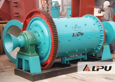
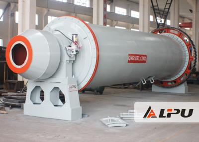
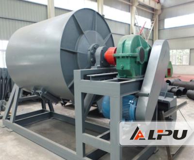
18.5kw Ceramic Ball Milling Equipment for Mineral Separation , Building Material
Introduction of Ball Mill
1. Ball Mill is applicable to all kinds of ores and other grinding materials, widely used in mineral separation, building materials, chemical and other industries.
2. According to the different way of grinding, it can be divided into open flow and circle flow.
3. According to the length diameter size of mill tube, it can be divided into: short grinding, medium-long grinding, long grinding (also called tube mill, the internal generally divided into 2-4 warehouse.
4. The feature of Tube Mill is high crushing scale, namely that product is fine, a strong compatible to material, fineness of product is easy to adjust, and easy to large-scale. So it is widely used in cement industry.
Application of Ball Mill
Cement, silicate products, new building materials, refractory material, chemical fertilizer, black and non-ferrous metal separation and glass ceramics production industry.
Structure of Ball Mill
The ball mill includes motor, reducer, slow drive, power distribution control cabinet, feeding device, main bearing, rotary body, discharging device, transmission parts, lubrication system (mainly including high pressure pump station and low pressure thin oil station) and other major parts. Hollow shaft with steel castings, lining systems can be replaced, return big gear uses the straight teeth, cast steel material, roll teeth processing. The cylinder body set have high chenban manganese steel and alloy element chilling wear resistance linings, good resistance to impact and abrasion resistance. This machine has smooth and reliable operation. Internal structure can be adjusted according to customer requirements.
Technical Data:
Model | Shell rotation speed(r/min) | Ball load(t) | Feeding size(mm) | Discharging size(mm) | Capacity | Motor power(kw) | Weight(t) |
(t/h) | |||||||
900×1800 | 36~38 | 1.5 | ≤20 | 0.075-0.89 | 0.65-2 | 18.5 | 5.5 |
900×3000 | 36 | 2.7 | ≤20 | 0.075-0.89 | 1.1-3.5 | 22 | 6.7 |
1200×2400 | 36 | 3 | ≤25 | 0.075-0.6 | 1.5-4.8 | 30 | 12 |
1200×3000 | 36 | 3.5 | ≤25 | 0.074-0.4 | 1.6-5 | 37 | 12.8 |
1200×4500 | 32.4 | 5 | ≤25 | 0.074-0.4 | 1.6-5.8 | 55 | 13.8 |
1500×3000 | 29.7 | 7.5 | ≤25 | 0.074-0.4 | 2-5 | 75 | 16.8 |
1500×4500 | 27 | 11 | ≤25 | 0.074-0.4 | 3-6 | 110 | 21 |
1500×5700 | 28 | 12 | ≤25 | 0.074-0.4 | 3.5-6 | 130 | 25.8 |
1830×3000 | 25.4 | 11 | ≤25 | 0.074-0.4 | 4-10 | 130 | 29 |
1830×4500 | 25.4 | 15 | ≤25 | 0.074-0.4 | 4.5-12 | 155 | 35.5 |
1830×6400 | 24.1 | 21 | ≤25 | 0.074-0.4 | 6.5-15 | 210 | 43 |
1830×7000 | 24.1 | 23 | ≤25 | 0.074-0.4 | 7.5-17 | 245 | 43.8 |
2100×3000 | 23.7 | 15 | ≤25 | 0.074-0.4 | 6.5-36 | 155 | 34.8 |
2100×4500 | 23.7 | 24 | ≤25 | 0.074-0.4 | 8-43 | 245 | 38 |
2100×7000 | 23.7 | 26 | ≤25 | 0.074-0.4 | 8-48 | 280 | 56.6 |
2200×4500 | 21.5 | 27 | ≤25 | 0.074-0.4 | 9-45 | 280 | 51.8 |
2200×6500 | 21.7 | 35 | ≤25 | 0.074-0.4 | 14-26 | 380 | 60 |
2200×7000 | 21.7 | 35 | ≤25 | 0.074-0.4 | 15-28 | 380 | 62 |
2200×7500 | 21.7 | 35 | ≤25 | 0.074-0.4 | 15-30 | 380 | 64.8 |
2400×3000 | 21 | 23 | ≤25 | 0.074-0.4 | 7-50 | 245 | 54 |
2400×4500 | 21 | 30 | ≤25 | 0.074-0.4 | 8.5-60 | 320 | 65 |
2700×4000 | 20.7 | 40 | ≤25 | 0.074-0.4 | 12-80 | 380 | 94 |
2700×4500 | 20.7 | 48 | ≤25 | 0.074-0.4 | 12-90 | 480 | 102 |
3200×4500 | 18 | 65 | ≤25 | 0.074-0.4 | Determined by process conditions | 800 | 137 |
3600×4500 | 17 | 90 | ≤25 | 0.074-0.4, | Determined by process conditions | 850 | 158 |
3600×6000 | 17 | 110 | ≤25 | 0.074-0.4 | Determined by process conditions | 1250 | 175 |
Product Picture Show: