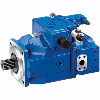
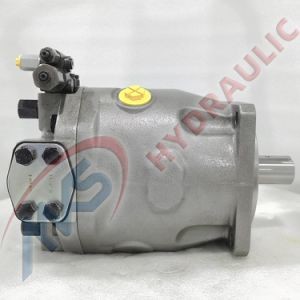
Features
– Variable displacement axial piston pump in swash plate design for hydraulic transmissions in closed circuits.
– The flow rate is proportional to the input speed and displacement. It can be infinitely adjusted by adjusting the swash plate.
– The required auxiliary pump and all necessary control valves are integrated.
– One common auxiliary pump for boost and EP control pressure
– Compact design (extremely short length)
– Good power/weight ratio
– Low noise level
– Long service life
– High efficiency
– New electrohydraulic control EP with proportional solenoid and zero displacement position (at power loss)
– Through-drive with multi-pump combination also available for integrated auxiliary pumps
Safety information
– Pump A4CSG is designed for operation in closed circuits.
– System design, installation and commissioning need to be carried out by trained technicians and dealers.
– All hydraulic ports may only be used to tighten hydraulic service lines.
– Tightening torques: Observe the manufacturer’s information on the maximum permissible tightening torques for the accessories used.
For fastening screws in accordance with DIN 13, it is recommended to check the permissible tightening torques in accordance with VDI 2230 (published in 2003) in each case.
– During or shortly after operation of the pump, the housing and especially the coils may be extremely hot, avoid burns!
Notes on installation and commissioning
During commissioning and operation, the pump housing must be filled with oil. Commissioning must be carried out at low speed and without load until the system is completely degassed
If stationary for a long period of time, the housing can leak oil through the service line. When restarting, the pump housing must be refilled with oil.
The inlet pressure at the suction port S must not fall below 0.8 bar (absolute)
Mounting position:
Optional.
To achieve a low noise level, all hydraulic lines (suction, pressure and discharge lines) should be connected to the tank via flexible fittings.
Avoid the use of non-return valves in the pump discharge line. If necessary, please contact us.
Ordering Model/Standard Products
01 | 02 | 03 | 04 | / | 05 | 06 | — | 07 | 08 | 09 | 10 | 11 | 12 | 13 | 14 |
A4CS | G | / | — | V | 35 | ||||||||||
Axial piston unit | |||||||||||||||
01 | Swash plate design, variable displacement pump, nominal pressure 350 bar, maximum pressure 400 bar | A4CS | |||||||||||||
Working Mode | |||||||||||||||
02 | Pumps, closed circuit | G | |||||||||||||
size | |||||||||||||||
03 | Collective displacement | 250 | 355 | 500 | 750 | ||||||||||
Control method | |||||||||||||||
04 | Hydraulic control system | With control valve | ● | ● | ● | ○ | HS5 | ||||||||
With proportional valve | ○ | ● | ● | ○ | EO2 | ||||||||||
Proportional control | Hydraulic control dependent on pilot pressure | ● | ● | ● | ● | HD.. | |||||||||
Electrohydraulic | ● | ● | ● | ● | EP.. | ||||||||||
series | |||||||||||||||
05 | Standard Models | ● | ● | ● | ● | 30 | |||||||||
Efficiency Optimized Models | ○ | ○ | ● | ○ | 33 | ||||||||||
Direction of rotation | |||||||||||||||
06 | View from the drive shaft | Clockwise | R | ||||||||||||
Counterclockwise | L | ||||||||||||||
Sealing material | |||||||||||||||
07 | FKM(Fluororubber) | ● | ● | ● | ● | V | |||||||||
NBR(Nitrile rubber),FKM(Fluororubber)Shaft seal ring | ○ | ○ | ○ | ○ | P | ||||||||||
transmission shaft | |||||||||||||||
08 | Keyed shaft according to DIN 6885 | ● | ● | ● | ● | P | |||||||||
Splined shafts according to DIN 5480 | ● | ● | ● | ● | Z | ||||||||||
09 | Based on ISO 3019-2 (Metric) | 4 holes | ● | ● | - | - | B | ||||||||
8 holes | - | - | ● | ● | H | ||||||||||
Working port | |||||||||||||||
10 | SAE flange ports A and B, laterally opposed, metric fastening threads | 35 | |||||||||||||
SAE flange port S, 90° offset from A and B, lateral, metric fastening thread | |||||||||||||||
Charge pump | |||||||||||||||
11 | With integrated charge pump | ● | ● | ● | ● | F | |||||||||
Without integrated charge pump | ● | ● | ● | ● | K |