Function | VM-1404-HD | |
System | Language | English / Chinese |
Operation Interface | Graphical User Interface (OSD menu) | |
Password Security | 2 Levels: Administrator or User | |
Video | Video Input | Supports 4 channels CIF/HD1/D1/960H/720P AHD camera Video input Supports 2-CH 720P AHD + 2-CH 960H analog mixing Video input Supports 1-CH 720P/1080P IPC + 4-CH 960H/D1/CIF Video input Note: 4 channels 720P AHD or 1-CH 720P/1080P IPC + 4-CH 960H Video input will require high speed SD card ( > 80Mb/S, Class 10 or higher) |
Video Output | 2 Channels (Front Panel 3.5mm Jack, Rear Panel on 24 pin I/O Port ) | |
Video Display | Single picture, 1~5 pictures | |
Signal System | PAL / NTSC ( PAL@100 frame 720P/sec; NTSC@120 frame 720P/sec ) | |
Image Compression | H.264 Main profile | |
Audio | Audio Input | 4 Channels |
Audio Output | 2 Channels (Front Panel 3.5mm Jack, Rear Panel on 24 pin I/O Port ) | |
Recording Format | Synchronized A/V recording | |
Recording & Storage | Image Resolution | CIF / HD1 / D1 / 960H / 720P/1080P optional |
Video Coding | ISO14496-10 Industry Standard | |
Video Bit Rate | CIF: 1536Kbps ~ 128Kbps, | |
HD1/D1: 2048Kbps ~ 400Kbps, | ||
960H: 2048Kbps ~ 400Kbps, | ||
720P:4096Kbps ~ 400Kbps | ||
1080P:4096Kbps ~ 400Kbps | ||
Select from 8 Levels of Video Image Quality ranging from 1(Highest) to 8(Lowest) | ||
Audio Bit Rate | 40Kbps | |
Storage | 2 SD Card Slots, Up to 128GB each, Class 10 or higher | |
Alarm | Alarm Input | 8 Channels, Select trigger for either less than 1VDC or greater than 5VDC |
Alarm Output | 1 Channel, 12V output | |
Communication Ports | RS485 | 1 Port for PTZ control or Data Device usage |
RS232 | 2 Port for communication or data usage | |
RJ45 Network | 1 Port of RJ45. For connection to an IP camera with maximun of 1080P | |
Wireless Communication* | 3G* | 3G (HSUPA / HSDPA / WCDMA / EVDO / TD-SCDMA) optional internal module |
4G* | 4G(TDD-LTE / FDD-LTE) optional internal module to match local cellular carrier | |
Wi-Fi* | Internal Wi-Fi 802.11b/g/n (2.4 / 5.8 Ghz) option | |
GPS* | Int'l Standard GPS* | Internal GPS module. Real-time geographic coordinates, speed information |
G-Sensor | Internal G-Sensor | Supports 3 Axis Motion Detection with user set ranges for X, Y and Z coordinates |
Software | PC Playback | A/V, GPS, Mapview, Speed, G-Sensor, etc. files available for playback on PC. Limited playback is also available on MDVR |
IVMS | Wireless (requires Wi-Fi or cellular Option) real-time A/V monitoring, GPS, alarms, etc. | |
Software Upgrade | Local or Remotely | Upgrade through SD card or remotely via IVMS platform |
Voltage Input | +8~+36V | 8~36VDC Please check operational voltage of vehicle prior to the installation of the MDVR and its accessories to prevent possible damage. |
Voltage Output | 12V | 12V(+/-0.2V),Max 3A |
ACC Detection | ≤4V | Power-off |
≥6V | Power-on | |
Video Input Resistance | 75Ω | 75Ω |
Video Output Voltage | 2Vp-p | 2VP-P CVBS output analog signal, screen input requires 75Ω resistance |
I / O Port | <1V | Low voltage trigger |
>5V | High voltage trigger | |
Operational Temperature | -25℃ ~ 75℃ | Install in well ventilated area, protected from moisture, heat, dust and vibration |
Dimensions | 170x142x50mm | Including Security Cover 170x187x50mm |
Features:
Common Questions and Answers (QA) for MDVR
Q: What shall we do when a problem that could not be solve occurs to the product?
A: Record product model and software version number and submit detailed problem description to our technical support engineer for analysis. Detailed description will be very helpful to our analysis.
Q: What shall we do when the mobile device has no video output?
A: 1. Check the power status of the device. If only one blue indicator is lit up, it indicates that the device is still in standby mode and not powered on; at the same time, check if red or yellow cable of the main power is supplied normally; If not, the device cannot be started.
2. Check if the display is powered and if the display video is switched to AV status.
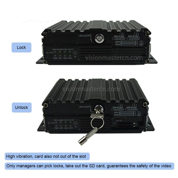
3. Check the connection status of the video output cable and display.4. Check the lock status the mainframe lock; the device can be started only when the lock is locked.