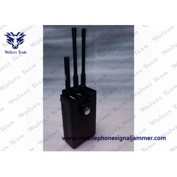
Specifications:
Isolating Signal Bandwidth
Output Interface | Output Frequency | RF Output |
CH1 | CDMA 800: 870 to 894MHz | 1-2W |
CH2 | GSM 900: 930 to 960MHz | 1-2W |
CH3 | PHS: 1805 to 1990MHz (DCS) | 1-2W |
CH4 | 3G: 2110 to 2170MHz | 1-2W |
CH5 | GPS 1400-1500MHz | 1-2W |
CH6 | WIFI 2400-2500MHz | 1-2W |
Total RF Power | 10Watt, +35dBm/2W | |
Power supply | AC110V/220V | |
Shielding area | Adjustable Radius 1~40 meters (Cellular signal must ≤-85dBm in the location), the jamming radius still depends on the strength signal in given area | |
Jammer Module Number | 6 | |
Safety Regulation | AC Adapter UL (E190582) CSA (LR112971 Level 3) | |
Weight | 4.00 Kg | |
Size (length x wind x high) | 330(L)×180(W)×80(H)mm (Not Include Antenna) | |
Humidity | 30%-95% | |
Running Temperature | -20 to +55 Celsius Degree |
Accessories
Just like other jammer products, this Adjustable High Power 6 Antenna WiFi & GPS & Cell Phone Jammer is mainly used in those places where using mobile phones is prohibited such as government, military, finance, security, police and command center etc. Also you can see themm at conference room, auditoriums, law court, library, exam room, school, cinema, theater, and hospital etc. This widely used jammer has been into the toppest list now.
If you are still troubled with the continuous dins of cell phone calls, but you have no idea about how to deal with such situation, then here will be your best choice. Come and buy one now!
1. Open the package
Carefully open the package, keep all package boxes for later shipment.
Check whether any fitting is good or not, if any damage happened, please contact with your provider.
The antennas and the RF output ports should be one-to-one connection by comparison of the top view. (The antenna must be firstly installed on the solid poles)
Input 220V AC by the power line link to power socket. (Switching on is not allowed before the all antenna have been linked, otherwise the equipment is easy to be damaged.)
· After connecting antennas. Turn on the switcher “on” position
· Press the on/off green button. The lights are on, and the jammer begins to work.
· Adjust the small switchers to control output power according to requirement
· Adjust the small switchers, knob to the minimum scale 0
· Press the on/off green button. The lights are off, and the jammer stops working.
· Turn off the switcher on “off” position
· Move away 220V power of the main machine.
· Move away Omni antennas.
· The jammer is out of work.