Up To 600Hz Variable Frequency Drive Electrical Motor Converters With CE
1. Description
The Up To 600Hz Variable Frequency Drive Electrical Motor Converters With CE is an advanced motor control solution that offers precise speed control for various industrial applications. This product is designed to meet the highest safety and quality standards, with a CE certification that ensures its reliability and performance.
The variable frequency drive electrical motor converters provide high efficiency and reduce power consumption, making it a cost-effective solution for businesses looking to improve their energy efficiency. With a frequency range of up to 600Hz, this product offers excellent flexibility in industrial processes.
The motor control system is easy to install and integrate, making it a versatile solution for businesses looking to upgrade their machinery. The product incorporates various protective measures, such as thermal protection and overload protection, to prevent damage to the motor or system.
Another unique feature of this product is its ability to operate at variable speeds, providing greater flexibility in industrial processes. This feature allows for precise control of the motor's speed, ensuring optimal performance and efficiency.
Overall, the Up To 600Hz Variable Frequency Drive Electrical Motor Converters With CE is a reliable and efficient solution for businesses looking to optimize their industrial processes. Its high-quality design, safety features, and variable frequency range make it an ideal choice for businesses looking to improve their energy efficiency and increase productivity.
2. Specifications
Model NO. | WN |
Control Mode | VIF control Sensorless fluxvector control(SVC)(Above3.7KW) Close-loop vector control(FVC)(Above 3.7KW) |
Maximum frequency | 0~600Hz |
Brand | Wannan Motor |
Carrier frequency | 0.5kHz~16kHz The carrier frequency is automatically adjusted based on the load features |
Input frequency resolution | Digital setting:0.01Hz Analog setting: Maximum frequency0.025% |
Start torque | GType:0.5Hz/150%(SVC); PType:0.5Hz/100% |
Speed range | 1:100(SVC) |
Speed stability accuracy | +0.5%(SVC) |
Overload capacity | G Type: 60s for 150% of the rated current3s for 180% of the rated current. P Type: 60s for 120% of the rated current. 3s for 150% of the rated current. |
Torque boost | Auto-boost; |
V/F Curve | Straight-line V/F curve |
V/F separation | 2 types:complete separation half separation |
Ramp Mode | Straight-line ramp Four groups of acceleration/deceleration time with the range of0.006500.0s |
DC Braking | DC braking DC braking frequency:0.00Hz~Maximum frequency Brakingtime:0.0s~36.0s Braking action current value:0.0%~100.0% |
JOG Control | JOGfreguencyrange:0.00Hz~50.00Hz JOG acceleration/deceleration time:0.0s~6500.0s |
Simple PLC,Multiple preset speeds | It implements up to 16 speeds via the simple PLC function or combination o terminal states |
Onboard PID | It realizes process-controlled closed loop control system easily |
Auto voitage regulation(AV.) | It can keep constant output voltage automatically when the mainsvoltage changes |
Overvoltage/overcurrent stall control | The current and voltage are limited automatically during therunning process so as to avoid frequent tripping due to over voltage/over current |
Rapid current limit | It helps to avoid frequent over current faults of the AC drive |
Torque limit and control | It can limit the torque automatically and prevent frequent over current tripping during the running process.Torque control can be implemented in the FVC mode. |
High performance | Control of asynchronous motor are implemented through the high-performance current vector control technology |
Rapid dip ride through | The load feedback energy compensates the voltage reduction so that the AC drive can continue to run for a short time |
Rapid current limit | It helps to avoid frequent over current faults of the AC drive |
Timing control | Timingrange:0.0Min~6500.0Min |
Communication methods | RS-485 |
Command source | Operation panel/Control terminals/Serial communication port You can perform switchover between these sources in various ways |
Frequency source | There are ten frequency sources Digital setting,analog voltage setting analog current setting pulse setting serial port setting You can perform switchover in various ways |
Auxiliary frequency source | There are ten auxiliary frequency sourcesIt can implement fine tuning o auxiliary frequency and frequency synthesis |
Input terminal | Standard: 4 digital input terminals(Below 5.5KW)/6 digital input terminals(Above7.5KW); 1 analog input terminal (Below 5.5KW)12 analog input terminals(Above 7.5KW); 1 voltage input (only support for 0~10Vabove 7.5KW),1voltage input(0~10V orcurrentinput(4~20mA) |
Output terminal | 1 High-speed pulse output terminal(Open-collector)(Above3.7KW 1 replay output terminal(Below5.5KW)/2replayoutput terminals(Above 7.5KW) 1 analog output terminal(3.7KW~5.5KW)/2 analog output terminal(Above 7.5KW),Support for 4~20mAcurrent output or 0~10V voltage output |
LED display | It displays the parameters |
Key locking and function selection | It can lock the keys partially or completely and define the function range o some keys so as to prevent mal-function |
Protection mode | Motor short-circuit detection at power-oninput/output phase loss protection over current protection, over voltage protection, under voltage protection overheat protection andoverload protection |
Installation location | Indoor, free from direct sunlight,dust,corrosive gascombustible gas,oi smoke,vapor, drip or salt. |
Transport Package | Carton/Wooden Case/Pallet |
Trademark | WNM |
Origin | China |
HS Code | 8501520000 |
Production Capacity | 2000PCS/Month |
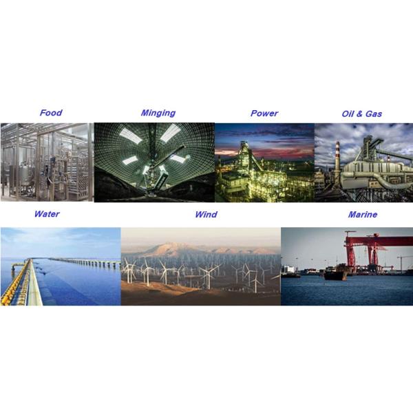
3. Applications
4. FAQ
A:We are a factory with 65 years (Since year 1958) manufacturing experience.