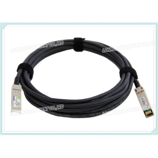
GEPON SFP OLT Transceiver SFE1243-P2+
FEATURES
Dual Wavelength Bi-Directional Tx/Rx
Single SC/PC receptacle optical interface compliant
1250 Mb/s Symmetrical Tx/Rx Data Rate
1490 nm CW Mode DFB Laser Transmitter
1310 nm APD/TIA Burst Mode Receiver
Digital Burst RSSI Function
Single 3.3 Volt DC supply
SFP Package Outline
Hot-pluggable
0 to 70 oC Operation
RoHs Compliance
APPLICATIONS
Gigabit Ethernet Passive Optical Networks OLT side
Fiber to the Home, Curb, Office (FTTx)
Point to Multi Point Service (P2MP)
Absolute Maximum Ratings | |||||
Parameter | Symbol | Min. | Max. | Units | Note |
Storage Temperature | Ts | -40 | 85 | ℃ | - |
Relative Humidity | RH | 5 | 90 | % | - |
Power Supply Voltage | Vcc | 0 | 3.6 | V | |
Soldering Temperature | - | - | 260 | ℃ | 10 seconds on leads only |
Receiver Damage Threshold | +4 | - | dBm |
Recommended Operating Conditions | |||||
Parameter | Symbol | Min. | Typ. | Max. | Units |
Power Supply Voltage | Vcc | 3.13 | 3.3 | 3.47 | V |
Operating Temperature | Top | 0 | - | 70 | ℃ |
Data Rate | - | - | 1250±100ppm | - | Mbps |
Power Supply Current | Icc | - | - | 350 | mA |
Transmitter Specifications (0oC < Top < 70oC, 3.1V < Vcc < 3.5V) | |||||
Parameter | Symbol | Min. | Typ. | Max. | Units |
Optical transmitter Characteristics | |||||
Optical Transmitter Power (EOL full temperature range) |
Po_EOL | +2 | - | +7 | dBm |
Power Off Transmitter Optical Transmitter Power | Poff | - | - | -39 | dBm |
Optical Center Wavelength | λC | 1480 | 1490 | 1500 | nm |
Output Spectrum Width | Δλ | - | - | 1 | nm(-20dB Width) |
Side Mode Suppression Mode | SMSR | 30 | - | - | dB |
Extinction Ratio | ER | 9 | - | - | dB |
Output Eye | Compliance with IEEE802.3ah | ||||
Optical Rise Time | tr | - | - | 0.26 | ns |
Optical Fall Time | tf | - | - | 0.26 | ns |
Relative Intensity Noise | RIN | - | - | -115 | dB/Hz |
Optical Return Loss | RL | - | - | 15 | dB |
Total Jitter | Tj | - | - | 0.43 | UI |
Optical Cross Talk | CRT | - | 40 | - | dB |
Transmit Reflectance | RFL | - | - | -12 | dB |
Transmit Dispersion Penalty | DP | - | - | 2.3 | dB |
Electrical Characteristics | |||||
Differential Input Voltage | VIH –VIL | 200 | - | 1600 | mV |
Differential Data input impedance | 80 | 100 | 120 | W | |
TX Disable Input Voltage – Low | TDIS, L | 0 | - | 0.8 | V |
TX Disable Input Voltage – High | TDIS, H | 2.0 | - | VCC | V |
TX Disable Assert Time | TASSERT | - | - | 10 | ms |
TX Disable Deassert Time | TDEASSERT | - | - | 1 | ms |
TX Fault Output Voltage -- Low | TFaultL | 0 | - | 0.8 | V |
TX Fault Output Voltage -- High | TFaultH | 2.0 | - | VCC | V |
Receiver Specifications (0oC < Top < 70oC, 3.1V < Vcc < 3.5V) | |||||
Parameter | Symbol | Min. | Typ. | Max. | Units |
Optical Receiver Characteristics | |||||
Maximum Input Power (Sensitivity) | Sen | - | - | -30 | dBm |
Maximum Input Power(Saturation) | PMAX | -6 | - | - | dBm |
Signal Detect -- Asserted | Pa | - | - | -31 | dBm |
Signal Detect -- Deasserted | Pd | -45 | - | - | dBm |
Signal Detect -- Hysteresis | Phys | 0.5 | - | 6 | dB |
Wavelength of Operation | λ | 1260 | 1360 | nm | |
Receiver Reflectance | RFL | - | - | -12 | dB |
Diagnostic Specification
Parameter | Range | Unit | Accuracy | Caliberation |
Temperature | 0~70 | oC | ±5oC | Internal |
Voltage | 3.1~3.5 | V | ±3% | Internal |
Bias Current | 0~100 | mA | ±10% | Internal |
Tx Power | 2 ~ 7 | dBm | ±3dB | Internal |
Rx Power | -30 ~ -7 | dBm | ±3dB | Internal |
Digital Diagnostic Memory Map
EEPROM Serial ID Memory Contents (A0h)
Data Address | Size (Bytes) | Name of Field | Contents(Hex) | Description |
0 | 1 | Identifier | 03 | SFP |
1 | 1 | Ext. Identifier | 04 | SFP function is defined by serial ID only |
2 | 1 | Connector | 01 | SC Connector |
3—10 | 8 | Transceiver |
00 00 00 00 10 10 01 00 |
Compatibility |
11 | 1 | Encoding | 01 | Encoding Type = 8B10B |
12 | 1 | BR, nominal | 0D | 1.25Gbps |
13 | 1 | Reserved | 00 | |
14 | 1 | Length(9um)-km | 14 | Transceiver transmit distance |
15 | 1 | Length (9um) | C8 | |
16 | 1 | Length (50um) | 00 | |
17 | 1 | Length (62.5um) | 00 | |
18 | 1 | Length (copper) | 00 | |
19 | 1 | Reserved | 00 | |
20—35 | 16 | Vendor name | 44 47 44 51 20 20 20 20 20 20 … 20 | “LIGHTECS”(ASCⅡ) |
36 | 1 | Reserved | 00 | |
37—39 | 3 | Vendor OUI | 00 00 00 | |
40—55 | 16 | Vendor PN | 44 47 2D 34 42 33 34 32 33 31 53 2D 30 31 20 20 | “SFE1243-P2+”(ASC II) |
56—59 | 4 | Vendor rev | 00 00 00 00 | |
60-61 | 2 | Wavelength | 05 D2 | Laser Wavelength = 1490 nm |
62 | 1 | Reserved | 00 | |
63 | 1 | CC BASE | xx | Check sum of bytes 0 - 62 |
64—65 | 2 | Options | 00 12 | TX_DISABLE, Lose of Single |
66 | 1 | BR, max | 05 | 5% |
67 | 1 | BR, min | 05 | 5% |
68—83 | 16 | Vendor SN | xx…xx | Programmed By factory |
84—91 | 8 | Vendor date code | xx…xx | Programmed By factory |
92 | 1 | Diagnostic type | 68 |
1,DDM Implemented 2,Internally calibrated |
93 | 1 | Enhanced option | 00 | |
94 | 1 | SFF-8472 | 03 | Rev10.2 SFF-8472 |
95 | 1 | CC_EXT | xx | Check sum of bytes 64 - 94 |
96—127 | 32 | Vendor specific | xx | Vendor Specific EEPROM |
128-255 | 128 | Reserved | Reserved for future use. |
EEPROM Serial ID Memory Contents (A2h)
Data Address | Size (Bytes) | Name of Field | Description |
Alarm and Warning Thresholds | |||
00-01 | 2 | Temperature High Alarm | Set to 90℃ |
02-03 | 2 | Temperature Low Alarm | Set to -30℃ |
04-05 | 2 | Temperature High Warning | Set to 85℃ |
06-07 | 2 | Temperature Low Warning | Set to -20℃ |