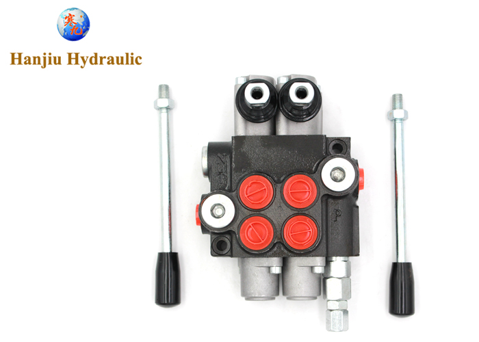
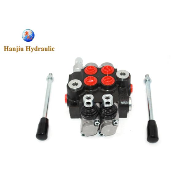
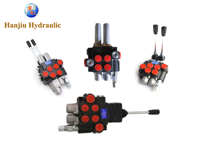
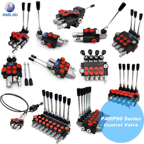
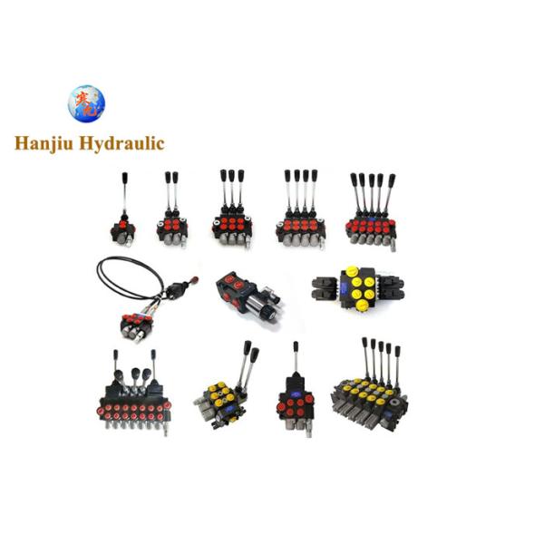
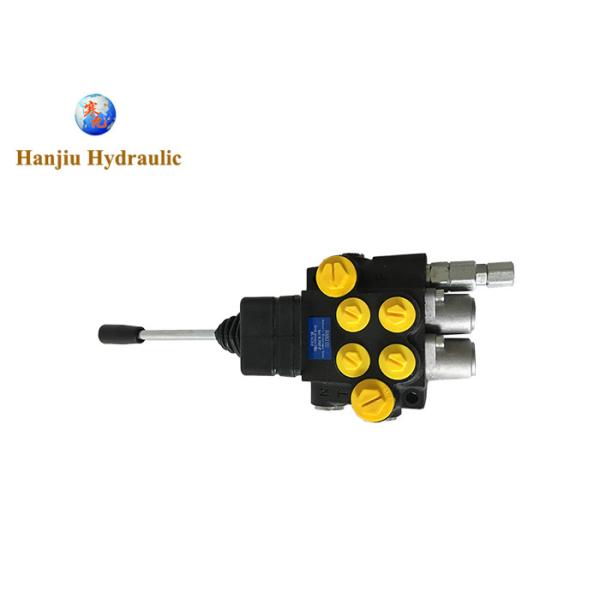
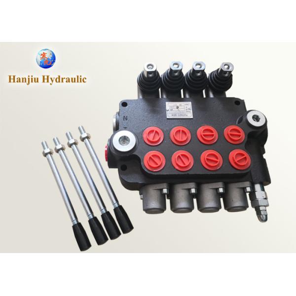
Chief P40 Valve Manual Hydraulic Directional Valve 40lts,45lts,60lts,80lts,120lts
The hydraulic directional valves is a valve that uses the spool to make relative movement in the inside of valve body to connect or cut off the oil circuit to change the direction of the oil flow.
The hydraulic directional valves is an integrated valve composed of a number of single-way hydraulic directional valve, safety relief valves,
one-way valves and charged valves.
It has the advantages of compact structure and low pressure loss.
The hydraulic directional valves control loop can manipulate the movement of multiple actuators, and is mainly used for construction machinery, lifting and transportation equipments and other mobile machinery that requires centralized manipulation of multiple actuators.
The control mode is mostly manual hydraulic directional valve. When the working pressure is high, the hydraulic pilot operated directional valve of the pressure reducing valve is adopted. According to the connection mode, the control circuit of the hydraulic directional valves is divided into three basic oil circuits: series, parallel, and series-parallel.
P40 series valves with middle-high pressure monoblock construction which is developed based on Europe technology.
Ambient temperature | -40C...+60C |
Viscosity | 12 ...800 mm2/s |
Fluid temperature | -15C...+80C |
Filtration | 10 to NAS 1638 |
Max operating pressure | 315 bar |
Back pressure | 50 bar |
Nominal flow | 40 l/min |
Spool stroke | 9 mm |
Actuating force | < 200 N |
Structure | 1-7sections |
Ports thread
BSP Thread | Metric thread | US standard UNF thread | US standard NTP thread | ||||
code | Thread size | code | Thread size | code | Thread size | code | Thread size |
G04 | G1/4 | M16 | M16X1.5 | U10 | 5/8-12UNF | N06 | NPT3/8 |
G06 | G3/8 | M18 | M18X1.5 | U12 | 3/4-16UNF | N08 | NPT1/2 |
G08 | G1/2 | M20 | M20X1.5 | U14 | 7/8-14UNF | N12 | NPT3/4 |
G12 | G3/4 | M22 | M22X1.5 | U16 | 1-12UNF | ||
M27 | M27X2 |
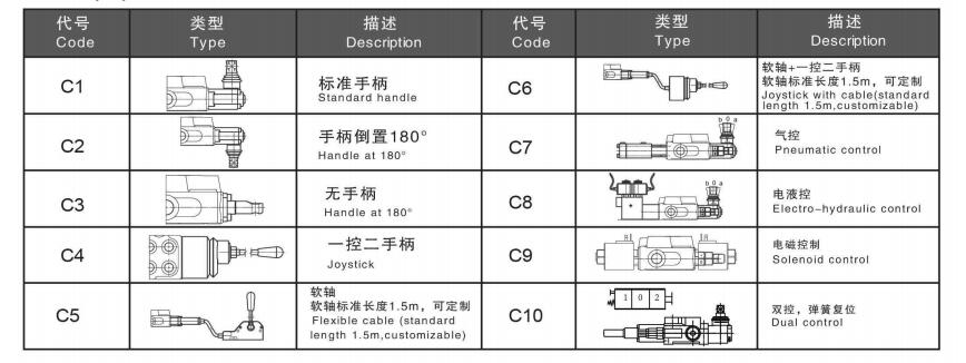
Control type:
Manually or mechanically controlled hydraulic directional control valve Р40 is designed for distribution and control of work flow between generator (pump) and executive mechanisms (cylinder, hydro-motor, etc.). It is manufactured with 1 to 7 plungers, with parallel or serial action, with common or individual back valve for each plunger, with or without safety valve.
1, Inner check valve: The check valve inside the valve body is to insure the hydraulic oil not to be returned.
2, Inner relief valve: The relief valve inside the valve body is able to adjust the hydraulic system working pressure.
3, Oil way: Parallel circuit, power beyond option
4, Control Way: Manual control, pneumatic control, hydraulic and electric control for optional.
5, Valve construction: monoblock construction, 1-7 levers.
6, Spool Function: O,Y, P,A.
7, Option: Hydraulic lock is available to be added on A and B port.
8, Available with manual, pneumatic control, electric and pneumatic control, hydraulic and electric control and etc.