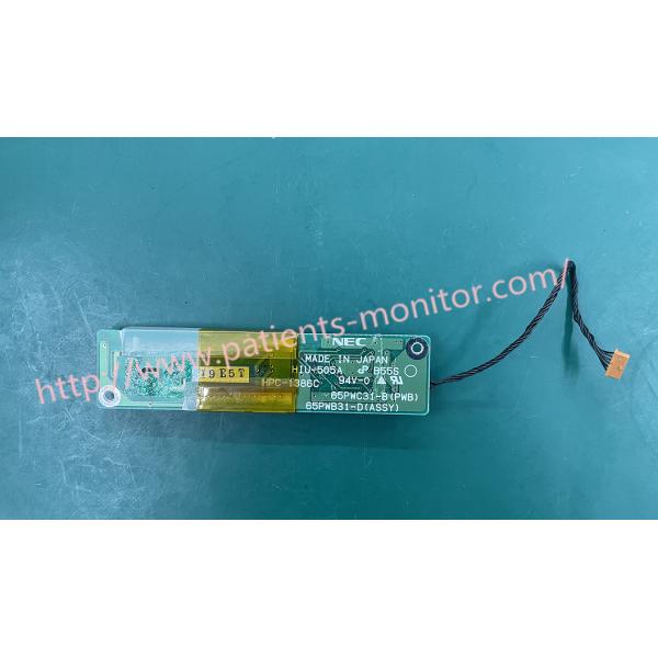
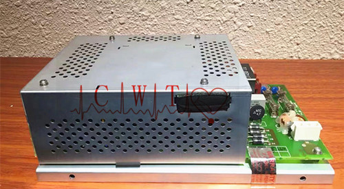
Zoll E Series Defibrillator Display inverter board (High Voltage Board) HPC-1386C HIU-505A 65PWC31-B(PWB) 65PWB31-D(ASSY)
About Zoll E Series Defibrillator Display inverter board (High Voltage Board) HPC-1386C HIU-505A 65PWC31-B(PWB) 65PWB31-D(ASSY)
The High Voltage (HV) module includes the high voltage circuitry required for pacing and defibrillation, including the defib charge circuitry, patient relay, safety relay, defib capacitor, defib choke and front end protection circuitry for the MFC ECG
The following table describes the high voltage board components:
Component | Function |
Solid State Patient Relay |
Controls the delivery of therapeutic energy to patient
|
Safety Relay |
Discharges Defib capacitor into the internal discharge resistor when defibrillator is not in use.
|
Defibrillator Capacitor |
Stores energy for therapy.
|
Defibrillator Choke |
Conditions waveform delivered to the patient.(DSW)
|
Front End Protection Circuitry for the MFC ECG |
Protects ECG front end against defibrillator pulses
|
High Voltage Capacitor Monitor
Before charging the pacemaker The high-voltage capacitor monitor performs a self-test to check the relay step by step. The step frequency relay
controls the configuration of the high voltage circuit to generate step frequency pulses or to charge the high voltage defibrillation capacitor.
Pacemaker capacitors are safely separated by resistors and relays to dissipate residual energy. When the main board is loaded This relay
outputs a low level XSAFREL signal. The safety relay is a polarized reed switch. The relay is driven by Q318. The stepper relay is driven by a
grounded source switch Q308 biased by R593. Q330 suppresses if XPACEREL is false. If XPACEREL is true, Q330 is turned off and Q308 is no
longer a terminal. The high-voltage capacitor is charged by converting the system's battery voltage into a high-voltage pulse using a transformer
T1. The basic operating frequency signal is used to switch the transistor Q1, which supplies current to the primary winding of the transformer T1
in the gate block of the motherboard. When charging a high-voltage capacitor, the main board independently monitors the voltage of the capacitor
via the VMON signal. If the main board detects an inadequate level, the system shuts down by setting SAFE high, which disables the SCR
discharge circuit and the flyback transformer driver.
The patient relay is discharged via the PATREL_DRV signal generated by XPATREL and Q304, Q323 and Q322 are disabled when XPACE_SEL
is logic low. After patient relay activation is complete, the main board outputs the XPATREL signal several hundred milliseconds later. A safety
relay closes to ensure complete dissipation of the high voltage capacitor energy. The pacer circuit generates and transmits user-controllable
pacing pulses to the pacing electrodes. to begin setting the pace Turn the front panel switch to the PACER position and set the OUTPUT and
RATE controls. The amplitude of the timer current is constant between pulses. and is determined by the position of the STIMULATOR OUTPUT
dial on the front panel. The heart rate is determined by the position of the PACER RATE dial on the front panel. The duration of the rhythmic pulse
was set to 40 ms.
Thank you so much for your attention .If you're interested in Zoll E Series Defibrillator Display Inverter Board (High Voltage Board) HPC-1386C HIU-505A 65PWC31-B(PWB) 65PWB31-D(ASSY ,feel free to contact us .Thank you .