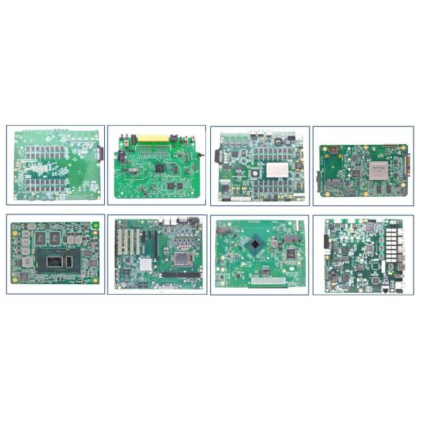
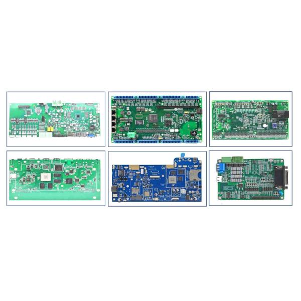
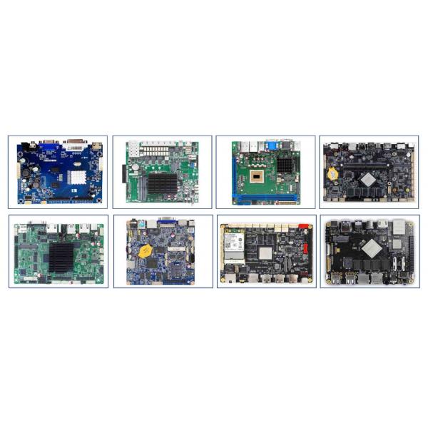
1.Product Information
The PCB materials industry has spent significant amounts of time developing materials that provide lowest possible signal loss for products with RF applications. For high speed and high frequency designs, losses will limit signal propagation distance and distort signals, and it will create an impedance deviation that can be seen in TDR measurements. As we design any printed circuit board and develop circuits that operate at higher frequencies, it may be tempting to opt for the smoothest possible copper in all designs you create.
While it is true that copper roughness creates additional impedance deviation and losses, how smooth does your copper foil really need to be? Are there other simple methods you can overcome some losses and still complete the routing you need in your PCB? In this article, we'll look at the balance between copper foil losses and other types of losses in a PCB, as well as some strategies that are commonly used to overcome roughness.
Before looking at which copper foil you should look for in your board, it's important to know something about the copper foil that actually available to be included in a PCB stackup. Copper foils are not something you always get to pick and choose to pair up with every laminate material. Some laminate manufacturers will provide multiple options that pair different types of copper foils with their material sets, but this is not the case with every laminate manufacturer or material. Unless you can procure materials separately and put them through a lamiantion process, you'll have to work within the material sets you can obtain from a lamiante manufacturer or distributor.
With this mind, here are the different types of copper foil you'll find in PCB materials:
Type of Copper | Description | Roughness |
Electrodeposited | Has a rougher surface on one side of the copper foil | Highest (above 1 um) |
Reverse treated | Uses a surface treatment to reduce roughness | Moderate (0.5 um to 1.5 um) |
Rolled-annealed | Has a smoother, denser surface from a rolling process | Low (0.25 to 0.5 um) |
Ultra-low profile | Additional treatments are used to reduce roughness | Lowest (comparable to rolled annealed, but can be less than 0.3 um) |
I would say the first important point in selecting the type of copper you'll use in your high-frequency PCB is to look at the loss budget for your highest frequency or highest bandwidth interconnects. For example, on an RF PCB, components that must source and receive an RF signal will have two specifications: transmitter output power and receiver sensitivity (or some similar names), both described in mW or in dBm. If you know an approximate board size or link length, you can get a pretty good estimate of the loss budget along one of your RF lines:
Loss Budget (dB) = [Tx Power (dBm)] - [Rx Sensitivity (dBm)]
This would be the total loss you can accept, although it's good to leave a few dB headroom above the Rx sensitivity value. Divide this by the length of the interconnect, and you now know the loss per length you can accept in your lines.
For high speed it's more complex because the signals do not have power and losses concentrated at a specific frequency. You can have high loss at high frequency, but as long as there is low loss in the receiver bandwidth range then the signal can be recovered at your receiver. Therefore, just like the case with input impedance, it's a good idea to select copper based by calculating losses at the bandwidth limit for your digital signals. This would be one of the following:
Nyquist frequency corresponding to the data rate
A value proportional to the inverse rise time (such as the knee frequency, or 0.35/(rise time))
Once you know the frequency that is important (either the carrier for RF boards or the bandwidth limit for digital boards), then you can move on to estimating losses and selecting copper.
When matching up copper and dielectric materials, there is a simple process that can be followed to ensure you hit your operating targets.
Plan out where you want to route the roughness-sensitive interconnects (surface layer vs internal layer), this will require a little bit of floorplanning with the major components
Determine the loss tangent you can accept at your operating frequency
After finding the material set that satisfies #2, look at your available copper options and choose the right copper roughness and surface plating for your design
Make sure the copper option you select in #3 is available in the weight you need; heavier copper will have lower skin effect losses
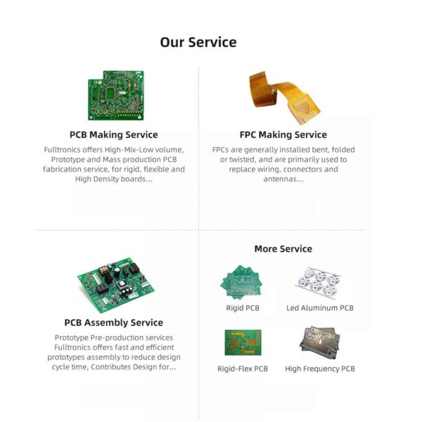
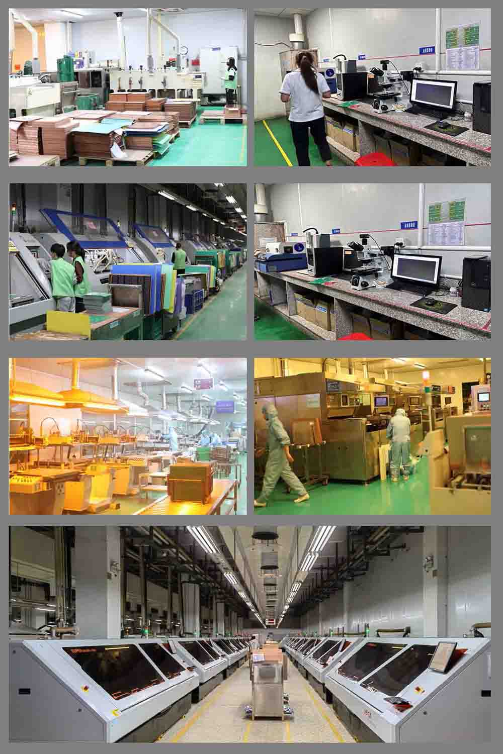
1. PCB fabrication.
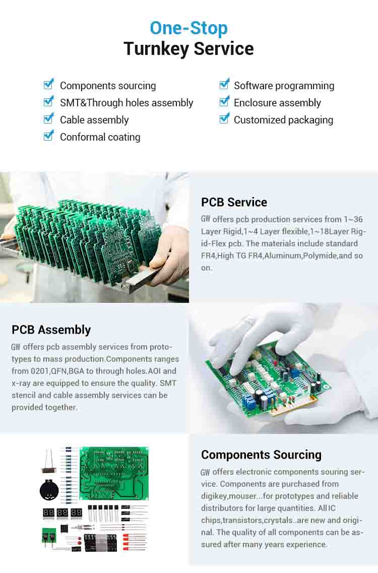
2. Turnkey PCBA: PCB+components sourcing+SMD and through-hole assembly
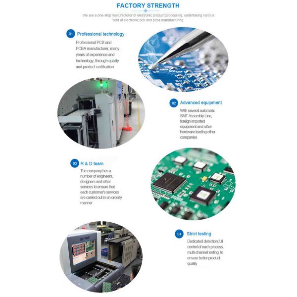
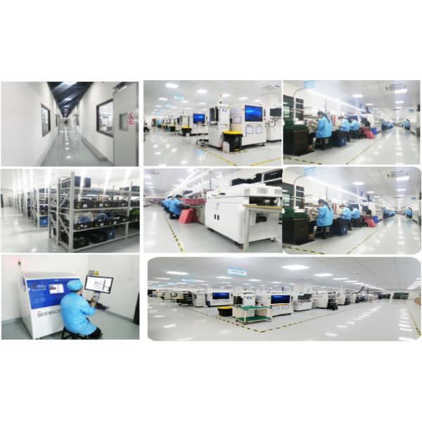
Global Well Electronic Inc. is a professional PCB solution supplier from Shenzhen, China, integrating PCB circuit board production and processing, STM processing and mounting, PCBA OEM, component purchasing, PCB/PCBA custom design-production- A comprehensive PCB circuit board company with one-stop turnkey service of processing-assembly-finished products. The company has a strong supply chain system, a professional and efficient collaborative team, a sound and complete quality control system, and the business philosophy of honesty and trustworthiness, customer first, and presents the products to everyone with low prices, reliable quality, high-quality service and after-sales service. client.
We provide total PCB solutions from PCB design to final mass production, including PCB fabrication and assembly, component sourcing, solder paste stencils, conformal coatings, and more. Serving the global electronics field, including industrial control, medical electronics, military equipment, power communication, automotive electronics, AI artificial intelligence, smart home and other industries.
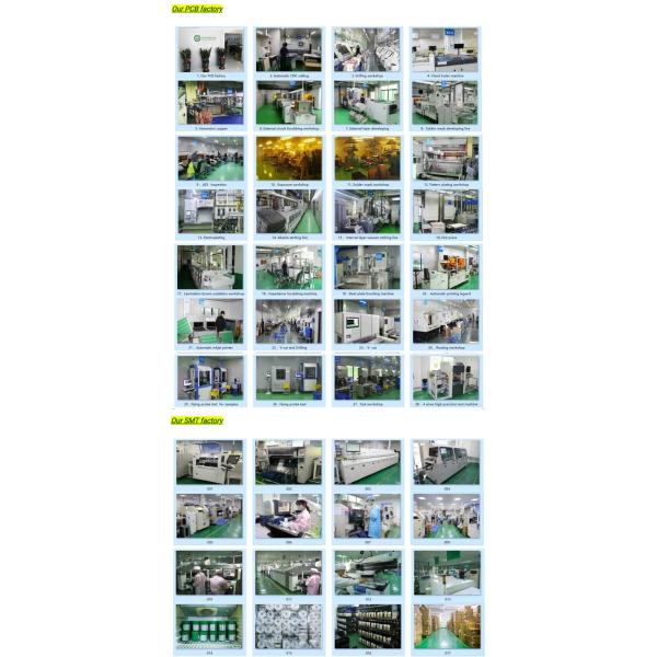
Our factory located in Shenzhen, and have almost 300
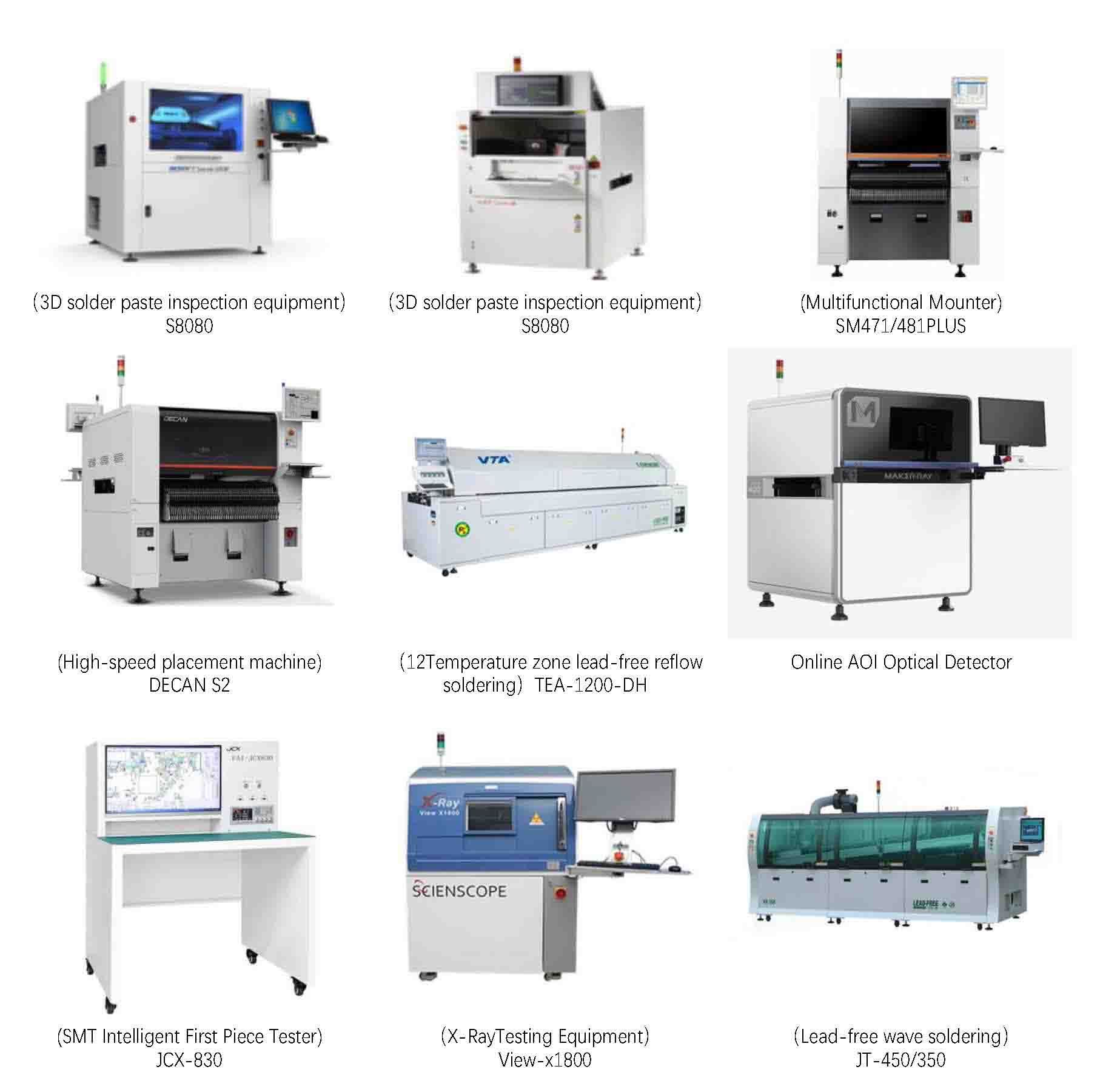
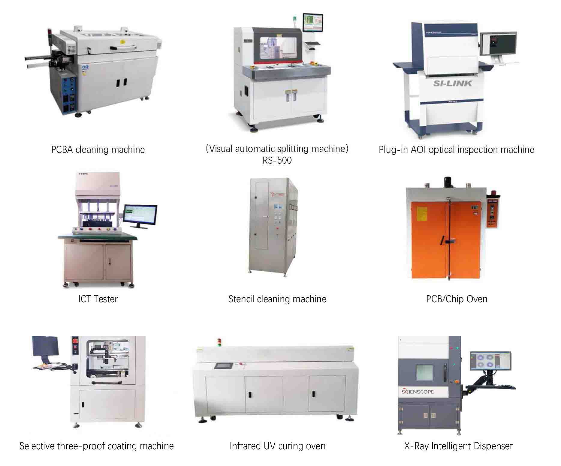
employees, more than 30 production lines include SMT, DIP, automatic welding, aging test and assembly. We have SMT machines from Japan and Korea, automatic solder paste printing machines, solder paste inspection machine(SPI)12 temperature zone reflow soldering machine, AOI detector, X-RAY detector, wave soldering machine, EM PCB ,dispenser,laser print machine etc., Different line configurations can meet requirements from small sample order to bulk shipment.
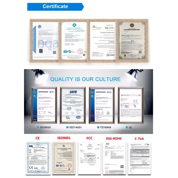
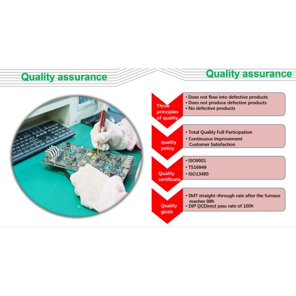
Our company has obtained ISO 9001 quality system certification and ISO 14001 system certification. With multi-testingprocedures, our products carry out the quality system standard strictly.
Order Quantity | 1-300,000,30000 Square Meter/Square Meters per Month module electronic board |
Layer | 1,2,4,6,upto 24 layer |
Material | FR-4,glass epoxy,FR4 High Tg,Rohs compliant,Aluminum,Rogers,etc |
PCB type | Rigid,flexible,rigid-flexible |
Shape | Any shape: Rectangular,round,slots,cutouts,complex,irregular |
Max PCB dimensions | 20inch*20inch or 500mm*500mm |
Thickness | 0.2~4.0mm, Flex 0.01~0.25'' |
Thickness tolerance | ± 10% |
Copper thickness | 0.5-4 oz |
Copper thickness tolerance | ± 0.25oz |
Surface finish | HASL,Nickle,Imm Gold,Imm Tin,Imm Silver,OSP etc |
Solder mask | Green, red,white,yellow,blue,black, Double-sided |
Silk screen | White,yellow,black,or negative, Double-sided or single-sided |
Silk screen min line width | 0.006'' or 0.15mm |
Min drill hole diameter | 0.01'',0.25mm.or 10 mil |
Min trace/gap | 0.075mm or 3mil |
PCB cutting | Shear,V-score,tab-routed |
Turnkey PCBA | PCB+components sourcing+assembly+package |
Assembly details | SMT and Thru-hole, ISO lines |
Lead Time | Prototype: 15 work days. Mass order: 20~25 work days |
Testing on products | Flying Probe Test, X-ray Inspection, AOI Test, functional test |
Quantity | Min quantity: 1pcs. Prototype, small order, mass order, all OK |
Files we need | PCB: Gerber files(CAM, PCB, PCBDOC) |
Components: Bill of Materials(BOM list) | |
Assembly: Pick-N-Place file | |
PCB panel Size | Min size: 0.25*0.25 inches(6*6mm) |
Max size: 20*20 inches(500*500mm) | |
PCB Solder Type | Water Soluble Solder Paste, RoHS lead free |
Components details | Passive Down to 0201 size |
BGA and VFBGA | |
Leadless Chip Carriers/CSP | |
Double-sided SMT Assembly | |
Fine Pitch to 0.8mils | |
BGA Repair and Reball | |
Part Removal and Replacement | |
Component package | Cut Tape,Tube,Reels,Loose Parts |
PCBA process | Drilling-----Exposure-----Plating-----Etaching Stripping-----Punching-----Electrical Testing-----SMT-----Wave Soldering-----Assembling-----ICT-----Function Testing-----Temperature - Humidity Testing |
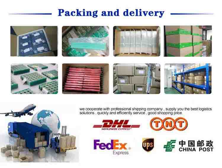
Packing details:
PCBA are packed into plastic bags. Plastic bags are put into small carton. 4 small carton into a big carton.
A big carton: 35×32×40 cm size.
Shipping Express:
FedEx, DHL, UPS, TNT, EMS, private lines, etc.
Air freight, Sea shipping
If you need help on PCB layout, you can contact us and send the board to us. We also provide Reverse Engineering Service.
We have been providing PCB Manufacture for many years in China,and we have rich experience in product production and product assembly.We believe our team will provide high quality and low cost service for you.
Thank you very much for all your support .
Best Regareds.
1. Gerber files of the bare PCB board
2. BOM (Bill of material) for assembly (please kindly advise us if there is any acceptablecomponents substitution.)
3. Testing Guide & Test Fixtures if necessary
4. Programming files & Programming tool if necessary
5. Schematic if necessary
A: Gerber or Eagle, BOM listing, PNP and Components Position
A: Yes, we can custom you sample to test before mass production
A: Within 6 hours for PCB quotation and around 24 hours for PCBA quotation.
A: 7-10 days for PCB production and components purchasing, and 10 days for PCB assembly and Testing