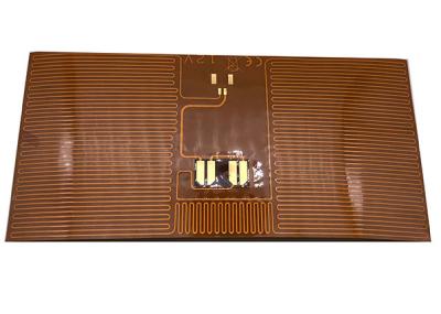
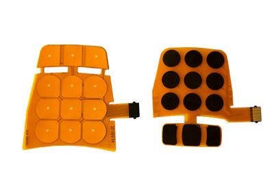
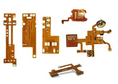
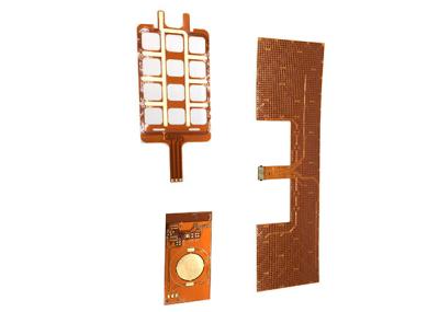
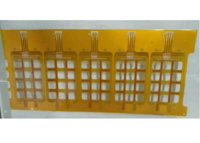
Enig Polyimide Flexible PCB Board Printed Circuit Board
-Definition
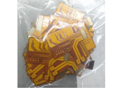
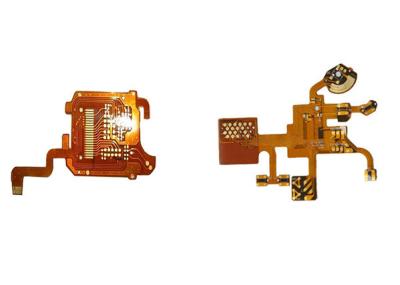
Flexible PCB – Flexible Printed Circuit, referred to as FPC.
A flexible printed circuit can be defined as an outline of conductive traces bonded on a flexible substrate. It is made into conductor circuit patterns using light pattern expose transfer and etching processes on the surface of a flexible substrate.
-Characteristics
Flex circuits widely used in mobile phones, cameras and smart wearable’s.
polyimide pcb can better fit wiring capability in spaces than the traditional rigid boards.Flexible circuit boards also have better resistance to high temperatures, shock and vibrations. polyimide copper flexible pcb has good performance with design challenges such as: unavoidable crossovers, specific impedance requirements, elimination of cross talk, additional shielding and high component density.
-Classify
Flexible PCB Manufacturing Process
-Double-side Flex-PCB:
Cutting → Drilling → PTH → Electroless Plating → Pretreating → Dry Film Lamination → Position → Exposure → Develop → Pattern Plating → Remove Dry Film → Pretreating → Dry Film Lamination → Position and Exposure → Develop → Etching → Remove Dry Film → Surface Finish → Cover lay Lamination → Lamination → Curing → Immersion Gold → Silkscreen → V-cutting/scoring → Electrical Test → Punching → FQC → Packaging → Shipment
-Single-side Flex-PCB:
Cutting → Drilling → Dry Film Lamination → Position and Exposure → Develop → Etching → Remove Dry Film → Surface Finish → Coverlay Lamination →Lamination → Curing → Surface Finish → Immersion Gold → Silkscreen → V-cutting/scoring → Electrical Test → Punching → FQC → Packaging → Shipment
Capacity
Raw material | Polymide, PET, PEN, FR4 |
Layer | 1 Layer-8 Layer |
Final Thickness | 0.002''-0.1'' (0.05-2.5mm) |
Surface finishing | Chemical Gold, Immersion Silver, Immersion Tin |
Max. Board size | 20.5'' x 13'' |
Min Trace/ Width | 1oz: 5mil/5mil (outer layer) |
Min Hole Ring | 1oz: 5mil |
Copper Thickness | 1/3oz-2oz |
Coverlay Color | White, Black, Yellow, Transparent |
Outline tolerance | +/-0.05mm |
Lead time
Category | Q/T Lead time | Standard Lead Time | Mass Production | |||
| ||||||
2 Layers | 24hrs | 3-4 working days | 8-15 working days | |||
| ||||||
4 Layers | 48hrs | 3-5 working days | 10-15 working days | |||
| ||||||
6 Layers | 72hrs | 3-6 working days | 10-15 working days | |||
| ||||||
8 Layers | 96hrs | 3-7 working days | 14-18 working days | |||
| ||||||
10 Layers | 120hrs | 3-8 working days | 14-18 working days | |||
| ||||||
12 Layers | 120hrs | 3-9 working days | 20-26 working days | |||
| ||||||
14 Layers | 144hrs | 3-10 working days | 20-26 working days | |||
| ||||||
16-20 Layers | Depends on the specific requirements | |||||
| ||||||
20+ Layers | Depends on the specific requirements |
FAQ:
Q1: How can I get a quotation:
. Please send gerber file with format: .PCB / .P-CAD / .DXP / .Gerber
Q2: Can you manufacture my PCBs from a picture file?
. Could you please provide a sample?
Q3: Do you have PCB in stock?
. Most of our PCB board are customized, which according to Gerber file.
. ABIS has samples in stock that could be sent to you for quality checking always.
Q4: What board manufacturer do you use for FR4?
. Main Suppliers(FR4): Kingboard (Hong Kong), NanYa (Taiwan), and Shengyi (China).
Q5: Will my PCB files be checked?
. Checked within 12 hours. Once Engineer's question and working file be approved, production will start.
Q6: What do you require in order to produce an assembly quotation?
. Bill of materials (BOM) detailing:
a), manufacturers parts numbers,
b), components suppliers' parts number (e.g. Digi-key, Mouser, RS )
c), PCBA sample photos if possible.
d), Quantity
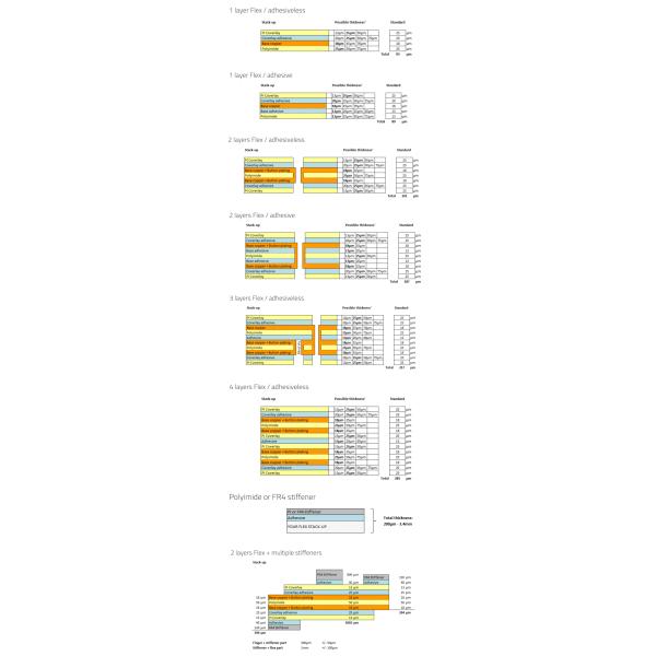
Flexible PCB Stack up
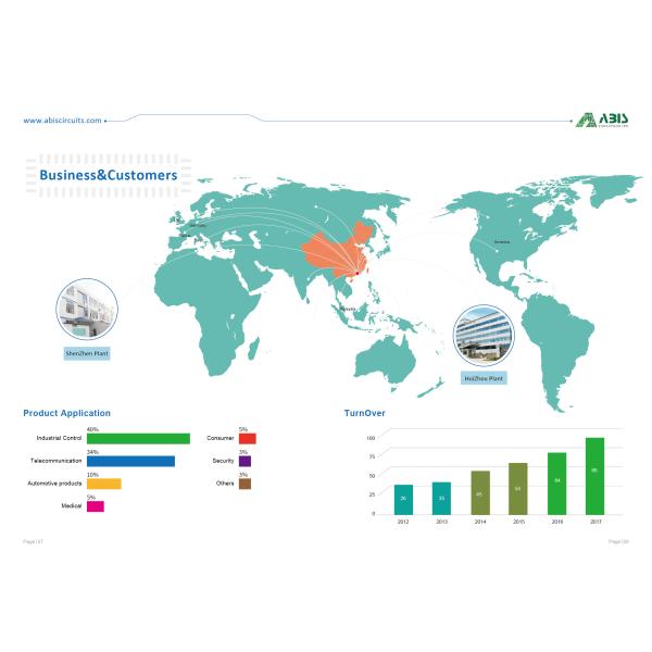
Buiness& Customers
ABIS cares every your order even 1 piece