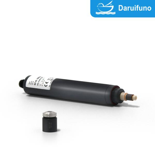
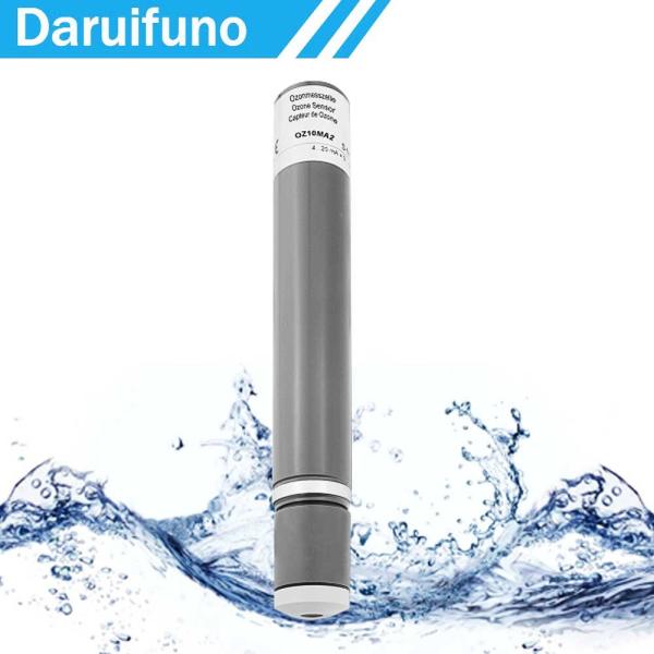
Two-Wire 4-20mA Two-Electrode Ozone Sensor For Drinking Water, Direct Drinking Water, Service Process Water
Two-electrode system ozone sensor OZ1.2, used in drinking water, direct drinking water, service and process water, measuring water without surfactant, optional range 0~0.5/2/5/10/20ppm
The functional characteristics of the ampere film ozone sensor include high sensitivity and fast response, which can accurately measure the ozone concentration in water. Its advantages are strong anti-interference ability, suitable for various water quality environments, and long service life. It is suitable for drinking water and industrial water treatment to ensure water quality safety.
Specifications
![]() |
OZ1.2 |
Indicator | Ozone |
Application | Swimming pool water, drinking water, service water, process water |
Measuring system | Membrane covered, amperometric 2-electrode system |
Electronic | Analog version: - voltage output - not galvanically isolated electronics - analog internal data processing - output signal: analog (analog-out/analog) Digital version: - electronic is completely galvanically isolated - digital internal data processing - output signal: analog (analog-out/digital) or digital (digital-out/digital) mA-version: - current output analog - not galvanically isolated electronics - output signal: analog (analog-out/analog) |
Information about the measuring range | The actual slope of a sensor can vary production-related between 65% and 150% of the nominal slope Note: With a slope > 100% the measuring range is reduced accordingly. (Ex.: 150% slope → 67% of the specified measuring range) |
Slope drift At repeatability conditions (25 °C, pH 7,2 in drinking water) | Approx. <- 1% per month |
Working temperature | Measuring water temperature: 0 … +45 °C (no ice crystals in measuring water) |
Ambient temperature: 0 … +55 °C | |
Temperature compensation | Automatically, by an integrated temperature sensor |
Max. allowed working pressure | Operation without retaining ring: - 0.5 bar - no pressure impulses and/or vibrations |
Operation with retaining ring in Flow cell: - 1.0 bar, - no pressure impulses and/or vibrations (see option 1) |
![]() |
OZ1.2 | |||
Flow rate (Incoming flow velocity) | Approx. 15-30 l/h (33 – 66 cm/s) in flow FLC, small flow rate dependence is given | |||
pH-range | pH 1 – pH 11 | |||
Run-in time | First start-up approx. 1 h | |||
Response time | T90 : approx. 15 sec. | |||
Zero point adjustment | Not necessary | |||
Calibration | At the device, by analytical determination | |||
Interferences | Cl2: factor 0.03 | |||
Absence of the disinfectant | Max. 24 h | |||
Connection | mV version: Modbus version: 4-20 mA version: | 5-pole M12, plug-on flange 5-pole M12, plug-on flange 2-pole terminal or 5-pole M12, plug-on flange | ||
max. length of sensor cable (depending on internal signal processing) | analog | < 30 m | ||
digital | > 30 m are permissible Maximum cable length depends on application | |||
Protection type | 5-pole M12 plug-on flange: IP68 2-pole terminal with mA-hood: IP65 | |||
Material | Semipermeable membrane, PVC-U, ABS | |||
Size | Diameter: Length: mV version Modbus version 4-20 mA version | approx. 25 mm approx. 190 mm (analog signal processing) approx.. 205 mm (digital signal processing) approx. 205 mm approx. 220 mm (2-pole-terminal) approx. 190 mm (5-pole-M12) | ||
Transport | +5 … +50 °C (sensor, electrolyte, membrane cap) |
![]() |
OZ1.2 |
Storage | Sensor: dry and without electrolyte no limit at +5 … +40 °C |
Electrolyte: in original bottle protected from sunlight at +5 … +35 °C min. 1 year or until specified EXP-Date | |
Membrane cap: in original packing no limit at +5 … +40 °C (used membrane caps can not be stored) | |
Maintenance | Regularly control of the measuring signal, min. once a week The following specifications depend on the water quality: Change of the membrane cap: once a year (depending on the water quality) Change of the electrolyte: every 3 - 6 months |
![]() |
Option 1: Retaining ring |
- When operating with pressures >0.5 bar in flow cell - Dimensions retaining ring 29 x 23.4 x 2.5 mm, slitted, PETP - Different positions for groove selectable(on request) |
| ![]() |
Technical Data
1. OZ1.2 (analog output, analog internal signal processing)
A potential-free electrical connection is necessary as the sensor electronic is not equipped with a galvanical
isolation.
![]() | Measuring range in ppm | Resolution in ppm | Output Output resistance | Nominal slope in mV/ppm | Voltage supply | Connection |
OZ1.2H-M12 | 0.005…2.000 | 0.001 |
0…-2000 mV 1 kΩ | - 1000 |
±5 - ±15 VDC 10 mA | 5-pole M12 plug-on flange
Function of wires: PIN1: measuring signal PIN2: +U PIN3: -U PIN4: signal GND PIN5: n. c. |
OZ1.2N-M12 | 0.05…20.00 | 0.01 | - 100 | |||
OZ1.2HUp-M12 | 0.005…2.000 | 0.001 |
0…+2000 mV 1 kΩ | +1000 |
10 - 30 VDC 10 mA | 5-pole M12 plug-on flange Function of wires:
PIN1: measuring signal PIN2: +U PIN3: power GND PIN4: signal GND PIN5: n. c. |
OZ1.2NUp-M12 | 0.05…20.00 | 0.01 | +100 |
(Subject to technical changes!)
2. OZ1.2 (analog output, digital signal processing)
Analog-out / digital
-The power supply is galvanically isolated inside of the sensor.
-The output signal is galvanically isolated too, that means potential-free.
![]() | Measuring range in ppm | Resolution in ppm | Output Output resistance | Nominal Slope in mV/ppm | Power supply | Connection |
OZ1.2H-An-M12 | 0.005…2.000 | 0.001 | analog 0…-2 V (max. -2.5 V) 1 kΩ | - 1000 |
9-30 VDC approx. 20-56 mA | 5-pole M12 plug-on flange
Function of wires: PIN1: measuring signal PIN2: +U PIN3: power GND PIN4: signal GND PIN5: n. c. |
OZ1.2N-An-M12 | 0.05…20.00 | 0.01 | - 100 | |||
OZ1.2H-Ap-M12 | 0.005…2.000 | 0.001 | analog 0…+2 V (max. +2.5 V) 1 kΩ | +1000 | ||
OZ1.2N-Ap-M12 | 0.05…20.00 | 0.01 | +100 |
(Subject to technical changes!)
3. OZ1.2 (digital output, digital signal processing)
-The power supply is galvanically isolated inside of the sensor.
-The output signal is galvanically isolated too, that means potential-free.
![]() | Measuring range in ppm | Resolution in ppm | Output Output resistance | Power supply | Connection |
OZ1.2H-M0c | 0.005…2.000 | 0.001 | Modbus RTU
There are no terminating resistors in the sensor. | 9-30 VDC
approx. 20-56 mA | 5-pole M12 plug-on flange Function of wires: PIN1: reserved PIN2: +U PIN3: power GND PIN4: RS485B PIN5: RS485A |
OZ1.2N-M0c | 0.05…20.00 | 0.01 |
(Subject to technical changes!)
4. OZ1.2 4-20 mA (analog output, analog internal signal processing)
A potential-free electrical connection is necessary as the sensor electronic is not equipped with a galvanical
isolation.
4.1 Electrical connection: 2 pole terminal clamp
![]() | Measuring range in ppm | Resolutio n in ppm | Output Output resistance | Nominal slope in mA/ppm | Voltage supply | Connection |
OZ1.2MA0.5 | 0.005…0.500 | 0.001 | 4…20 mA uncalibrated | 32.0 |
12…30 VDC RL 50Ω…RL 900Ω |
2-pole terminal (2 x 1 mm²)
Recommended: Round cable 4 mm 2 x 0.34 mm² |
OZ1.2MA2 | 0.005…2.000 | 0.001 | 8.0 | |||
OZ1.2MA5 | 0.05…5.00 | 0.01 | 3.2 | |||
OZ1.2MA10 | 0.05…10.00 | 0.01 | 1.6 | |||
OZ1.2MA20 | 0.05…20.00 | 0.01 | 0.8 |
(Subject to technical changes!)
4.2 Electrical connection: 5 pole M12 plug-on flange
![]() | Measuring range in ppm | Resolution in ppm | Output Output resistance | Nominal slope in mA/ppm | Voltage supply | Connection |
OZ1.2MA0.5-M12 | 0.005…0.500 | 0.001 | 4…20 mA uncalibrated | 32.0 | 12…30 VDC RL 50Ω…RL 900Ω | 5-pole M12 plug- on flange
Function of wires: PIN1: n. c. PIN2: +U PIN3: -U PIN4: n c. PIN5: n. c. |
OZ1.2MA2-M12 | 0.005…2.000 | 0.001 | 8.0 | |||
OZ1.2MA5-M12 | 0.05…5.00 | 0.01 | 3.2 | |||
OZ1.2MA10-M12 | 0.05…10.00 | 0.01 | 1.6 | |||
OZ1.2MA20-M12 | 0.05…20.00 | 0.01 | 0.8 |
(Subject to technical changes!)
Spare Parts
Type | Membrane cap | Electrolyte | Emery | O-ring |
For all OZ1.2 | M20.2 | EOZ1/W, 100 ml Art. no. 11101 | S1 | 14 x 1.8 silicone |
(Subject to technical changes!)