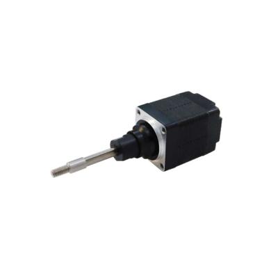
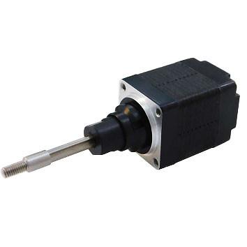
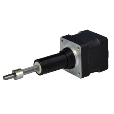
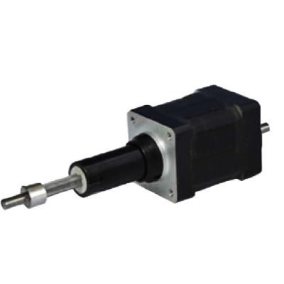
1. Hybrid Linear Motor Overview
Hybrid linear stepper motor is a precision transmission device that converts the motor rotor round rotation movement into a linear motion. It uses the coordination of the screw rod and the stepping motor to convert the rotation movement of the step motor into a linear motion of the screw, thereby achieving precise control of displacement.
Hybrid linear stepper motors are characterized with the advantages of high precision, high speed and high rigidity. Its accuracy can reach micron level, and the speed can reach several meters or even more than ten meters per minute. In addition, strong carrying capacity, simple structure, and convenient and even free of maintenance.
When selecting a hybrid linear motor, need to choose the appropriate screw type and specifications to meet different application scenarios and load needs, also the mechanical dimensions, driver current, etc.
2. Hybrid Stepper Motor Naming Rules and General Technical Specifications
Linear stepper motor naming rules,
General Specifications,
Step Angle | 1.8° (2 Phase) |
Step Angle Accuracy | ±0.09° |
Size | Nema 17, 42mm |
Insulation Grade | 500VDC, 20 MΩ Min. ,Class B |
Dielectric Strengt | 500 VAC for 1 Minute |
Temperature Rise | Less than 80℃ (Rated Current) |
Suface Temperature | Max.Allowed 100℃ |
Humidity Range | 20% to 90% RH |
IP Grade | IP40 |
Certificates | Rohs, CE, CCC |
3. 20LHS0494/0244/0164 Captive Type Hybrid Linear Stepper Motor Performance Datasheet
Model Name | Wiring | Rated Voltage | Rated Current | Resistance /phase | Inductance /phase | Power Consumption | Temp. Rise | Weight | Insulation Resistance |
42LHS2604 | Bipolar | 2.33V | 2.6A | 0.9Ω | 1.33mH | 14W | 75℃ | 352g | 20MΩ |
42LHS1304 | 5V | 1.3A | 3.8Ω | 6.6mH | |||||
42LHS0554 | 12V | 0.55A | 21.9Ω | 45.1mH |
Note: Customization of motor specifications available.
Available leadscrew specifications,
Code | Leadscrew Thread Dimensions in mm | ||
diameter | step | lead | |
N | φ5.54 | 0.003048 | 0.6096 |
J | φ5.54 | 0.012192 | 2.4384 |
Q | φ5.54 | 0.024384 | 4.8768 |
R | φ5.54 | 0.048768 | 9.7536 |
P | φ6.35 | 0.0039688 | 0.79375 |
A | φ6.35 | 0.0079375 | 1.58750 |
B | φ6.35 | 0.0158750 | 3.17500 |
C | φ6.35 | 0.0317500 | 6.35 |
4. Mechanical Dimensions (in mm)
Double Shaft Captive Type Mechanical Drawings as bellow,
Note: Above A,B available customization information as bellow,
Distance Code | Distance (mm) | A (mm) | B (mm) |
302 | 12.7 | 19.8 | 0.51 |
303 | 19.1 | 26.2 | 6.86 |
304 | 25.4 | 32.5 | 13.21 |
305 | 31.8 | 38.9 | 19.56 |
306 | 38.1 | 45.2 | 25.91 |
307 | 50.8 | 57.9 | 38.61 |
5. Force and Pulse Rate Curves
6. Wirings