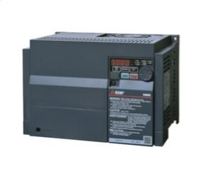
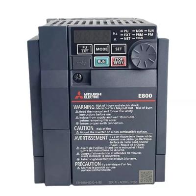
FR-E840-0060-4-60 Mitsubishi FR-E800 Series 2.2kw and 3 Phases Frequency Inverter

FR-E800 series is an economical high-performance network-type vector inverter, built-in corresponding to a variety of networks, and can realize linear connection.
| Series | FR-E800 SERIES |
| Type | FR-E800 RS485 INVERTER |
| Minimum Rated Voltage (V) | 380 |
| Min. Permissible Voltage (V) | 323 |
| Maximum Rated Voltage (V) | 480 |
| Max. Permissible Voltage (V) | 528 |
| Current Type | AC |
| Phases | 3 |
| Rated Output Current LD (A) | 6,9 |
| Rated Output Current ND (A) | 6 |
| Rated Motor Capacity LD (kW) | 3 |
| Rated Motor Capacity ND (kW) | 2,2 |
| Control Method | V/F CONTROL, REAL SENSORLESS VECTOR CONTROL, PM SENSORLESS VECTOR CONTROL, MAGNETIC FLUX VECTOR CONTROL |
| Motor Type | INDUCTION MOTOR, PM MOTOR |
| Brake Chopper ED (%) | 100 |
| Integrated EMC Filter | NO |
| Safe Torque Off (STO) | YES |
| Regenerative (4Q) | NO |
| Integrated DC Choke | NO |
| Display | BUILT-IN |
| Display Type | 4-DIGIT LED |
| PLC Function | YES |
| Program Memory | 2K |
| Program Memory Unit | STEPS |
| Integrated Digital Inputs | 7 |
| Digital Outputs (Transistor) | 2 |
| Digital Outputs (Relay) | 1 |
| Integrated Analogue Inputs | 2 |
| Integrated Analogue Outputs | 1 |
| IO Type of Terminal Block | SPRING CLAMP |
| Expandable | YES |
| RS-485 | 1 |
| USB | 1 (MINI B) |
| Ethernet Port | NO |
| Built-In Network | MODBUS RTU |
| Leakage Current (mA) | 1,2 |
| Power Loss LD (W) | 88 |
| Power Loss ND (W) | 75 |
| Frequency Range (Hz) | 0,2–590 |
| Protection Class | IP20 |
Product Dimensions & Weight
| Width (mm) | 140 |
| Height (mm) | 150 |
| Depth (mm) | 135 |
| Weight (kg) | 1,8 |
Conformity
| CE | COMPLIANT |
| UL/cUL | COMPLIANT |
| EAC | COMPLIANT |
| UKCA | COMPLIANT |
Installation of the inverter
Inverter placement
- Remove the front cover (or the lower front cover) and wiring cover to fix the inverter.
- Install the inverter on a strong surface securely with screws.
- Leave enough clearances and take cooling measures.
- Avoid places where the inverter is subjected to direct sunlight, high temperature and high humidity.
- Install the inverter on a nonflammable wall surface.
- When encasing multiple inverters in an enclosure, install them in parallel as a cooling measure.
Installation orientation of the inverter
Install the inverter on a wall as specified. Do not mount it horizontally or in any other way.
- Above the inverter Heat is blown up from inside the inverter by the small fan built in the unit. Any equipment placed above the inverter should be heat resistant.
- Arrangement of multiple inverters When multiple inverters are placed in the same enclosure, generally arrange them horizontally as shown in the figure (a). When it is inevitable to arrange them vertically to minimize space, take such measures as to provide guides between the inverters since heat generated in the inverters in bottom row can increase the temperatures in the inverters in top row, causing inverter failures.