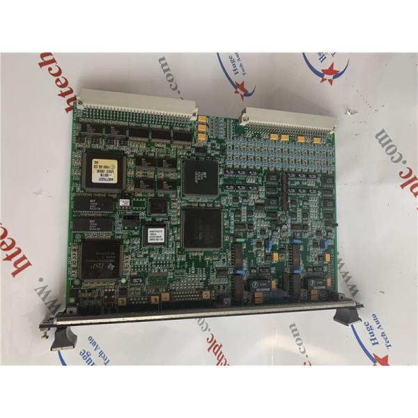
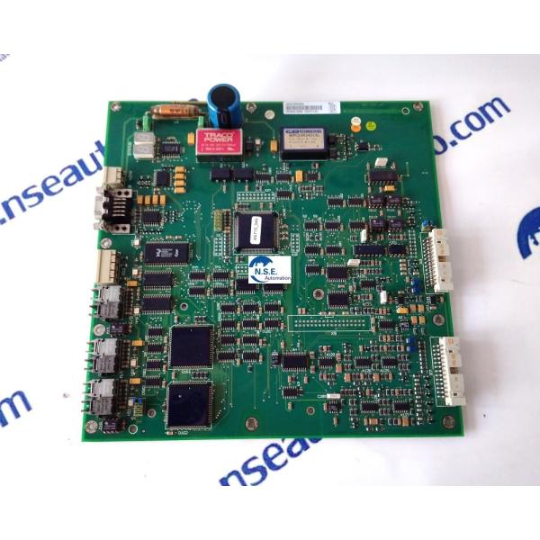
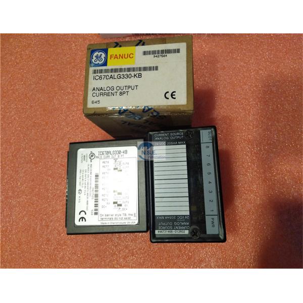
GE IC200ALG320 Analog Input Module, 12-Bit Voltage/Current, 4 or 8 Channels
Product Description:
Analog Input Module IC200ALG230 / BXIOAI4 provides an interface to either 4 voltage inputs or 4 current inputs. Analog Input Module IC200ALG260 / BXIOAI8 provides an interface to either 8 voltage inputs or 8 current inputs. ANALOG INPUT 12BIT VOLT/CURR CH The module receives power from the backplane power supply. No external power source is required for module operation. Power for the user’s transceivers must be supplied from an external source.
Relevant models: | ||
IC660BBD120 | IC670GBI002 | IC200CHS022 |
IC660BSM021 | IC670MDL241 | IC200ALG320 |
IC660TBD024 | IC670MDL740 | IC200ERM002 |
IC660BBA020 | IC670ALG230 | IC200PBI001 |
IC660BBA025 | IC670ALG320 | IC693APU300 |
IC660BBA026 | IC670ALG630 | IC693CHS398 |
IC660BBD020 | IC670CHS001 | IC693CMM321 |
IC660BBD021 | IC697BEM731 | IC693APU301 |
IC660BBD024 | IC697CHS750 | IC693CHS392 |
IC660BBD025 | IC697CMM742 | IC693MDL340 |
IC660BBD110 | IC697CPU731 | IC693MDL645 |
IC660BBA020 | IC697CPX772 | IC693MDL740 |
IC660BBA025 | IC697MDL653 | IC693PBM200 |
IC660BBA026 | IC697MDL753 | IC693BEM331 |
IC660BBD020 | IC697PWR710 | IC694TBB032 |
IC660BBD021 | IC698CPE010 | IC694MDL645 |
IC660BBD024 | IC698CPE020 | IC694MDL742 |
IC660BBD025 | IC698ETM001 | IC695PBM300 |
IC660BBD110 | IC698CHS117 | IC695ACC400 |
Diagnostics
The module reports a Loss of Internal Power fault for field-side circuits.
LED Indicators
The green INT PWR LED indicates the presence of internally-generated field power for the analog field-side circuits. The green OK LED is on when backplane power is present to the module.
Configuration Parameters
Two jumpers on the carrier terminals can be used to configure voltage or current mode and unipolar or bipolar operation in voltage mode. One jumper selects either voltage or current operating mode. With this jumper connected, the module accepts current inputs in the 4mA to 20mA range. With no jumper installed the module accepts -10VDC to +10VDC inputs. In voltage mode, another jumper on the carrier can be used to select the 0 to 10VDC range.
Preinstallation Check :
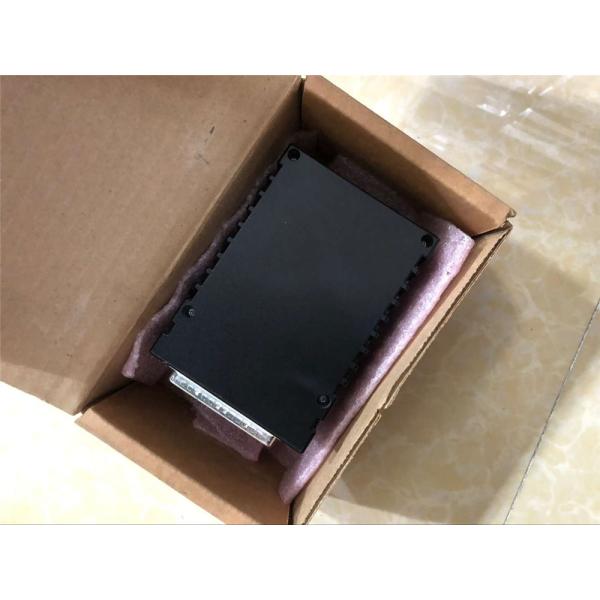
Carefully inspect all shipping containers for damage. If any equipment is damaged, notify the delivery service immediately. Save the damaged shipping container for inspection by the delivery service. After unpacking the equipment, record all serial numbers. Save the shipping containers and packing material in case it is necessary to transport or ship any part of the system.
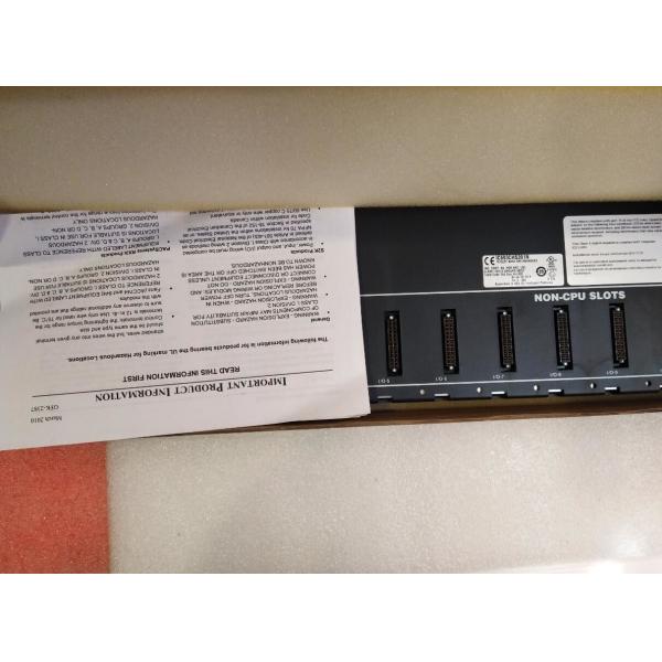
Reference pictures:(Please contact us for detailed photos!)